|
»Click here to display Table of Contents«
|

Subsequent Tucks |

|

|

|

|
|
Subsequent Tucks |
|
|
|

|
|
»Click here to display Table of Contents«
|
Subsequent Tucks |
|
|
|
|
|
Subsequent Tucks |
|
|
|
|
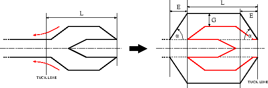
Figure 25: The shape of a complex tuck fold.
This case is more complicated than the preceding one because the final thickness of the airbag's receiving part depends on the thickness of the part to be inserted.
It is assumed that the tuck line (in fact, the symmetry plane) cuts the airbag in such a way that the airbag's thickness at the intersection is the same as the thickness of the receiving part (on the "positive" side of the symmetry plane). Otherwise, the program will refuse to execute the operation.
It is important to pay attention to the fact that the tuck line should not be placed too close to the wider part if initial penetrations need to be avoided.
In that case, a third parameter similar to maximum ![]() in the simple fold case is needed. As in the previous case, its role is to limit the slope of the diagonal parts close to the fold ends. Should the slope of the diagonal parts exceed this value, E will be increased to avoid this situation.
in the simple fold case is needed. As in the previous case, its role is to limit the slope of the diagonal parts close to the fold ends. Should the slope of the diagonal parts exceed this value, E will be increased to avoid this situation.
If the "inserted" part is not centered around the mid-plane of the receiving part, the width of the latter will be increased sufficiently in order to contain everything without creating intersections. The receiving part will remain centered around its mid-plane.
In the case where ![]() only two sloped parts will be created. There will be no "horizontal" part between the plans corresponding to E and L .
only two sloped parts will be created. There will be no "horizontal" part between the plans corresponding to E and L .