|
»Click here to display Table of Contents«
|

Basic Notions |

|

|

|

|
|
Basic Notions |
|
|
|

|
|
»Click here to display Table of Contents«
|
Basic Notions |
|
|
|
|
|
Basic Notions |
|
|
|
|
Although an actual airbag is not flat, for the purposes of this program, an airbag is defined as a set of surfaces, each of which is defined by its outline. This definition regards an airbag as being composed of pieces of flat fabric which can be folded.
In order to fold the airbag, more information is required:
| • | Airbag's mean plane - Although the program is able to compute the airbag's mean plane itself, it is preferable that this information be entered explicitly. The plane may be defined by three nodes or by a node and a vector (perpendicular to the plane). The planes are considered oriented, that is, they have a normal vector. In the airbag's main plane definition, the important information is its normal vector because it is used to determine the symmetry plane for folding (see The fold line below). It does not affect the fold definition if the airbag's mean plane is shifted (no rotation) because the program shifts the mean plane in the direction of its normal vector to place it just above the airbag. |
| • | The fold line - This line does not necessarily lie on the airbag's mean plane. It is used to define the symmetry plane, that is, the plane that will cut the airbag to the "left'' and "right'' sides. The symmetry plane is perpendicular to the airbag's mean plane and it contains the fold line. This definition applies when the fold line is not perpendicular to the airbag's mean plane. If the fold line and the airbag's mean plane are perpendicular, the program generates an error message. In any case, the fold line should be more-or-less parallel to this plane—the program generates a warning message when the angle between them is greater than 30°. As the fold line is oriented, the orientation of the symmetry plane can also be computed using the formula (see the Figure 20): |
![]()
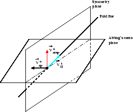
Figure 20: The fold line and the symmetry plane.
Once the symmetry plane is computed, the surfaces selected to be folded are cut by this plane.
In the following paragraphs, a convention is used in which the distance of a point from a plane is a signed number. This distance is the ordinary distance when the point is on the side pointed by the plane's normal vector and it is the negative of the distance in the opposite case.
Figure 21 indicates (in simplified form) what parts of the airbag are modified: the "negative'' (with respect to the symmetry plane) side of the airbag is folded and the "positive'' one remains in its place. The latter may; however, be slightly modified; for example, it may become thicker in order to be able to receive the folded side (simple tuck type fold). The exact way that the folded part is deformed depends on the fold type: it is either some kind of rotation in the "positive'' (with respect to the mean plane) direction (in the case of the simple fold) or else it is symmetrical (simple tuck fold).
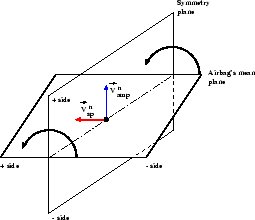
Figure 21: The direction of the fold.
As the symmetry plane is an internal object and it is not shown to you, it is easier to imagine the sense of folding using the fold line direction and the airbag's mean plane normal vector. Figure 22 gives two examples which will be useful in most of cases.
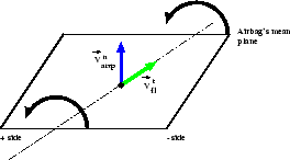
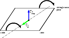
Figure 22: The direction of the fold vs. the fold line.