|
»Click here to display Table of Contents«
|

Translate panel |

|

|

|

|
|
Translate panel |
|
|

|

|
|
»Click here to display Table of Contents«
|
Translate panel |
|
|
|
|
|
Translate panel |
|
|
|
|
Use the Translate panel to move entities in a single specified direction. All selected entities move the same distance and parallel to each other.
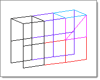
Selected entities highlight as shown above. |
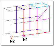
In this example, the translation will occur in the direction from N1 to N2. |
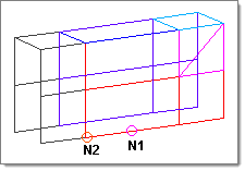
In this example, the selected elements have moved in the direction of N1 to N2. |
There are no subpanels on the Translate panel. All inputs and command buttons are located on the main panel.
Input |
Action |
||||||
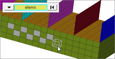
entity selector |
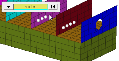
Select entities for translation. Valid entity types include nodes, elements, components, lines, surfaces, systems, groups, points, multibodies, ellipsoids, multibody planes, solids, blocks, and connectors. When you select nodes or elems, click the switch to change the selection mode.
|
||||||
coordinate system |
Choose between coordinate system types: global system and local system. Use global system to translate entities relative to the global coordinate system; Use local system to translate entities relative to a local coordinate system. Local systems can be rectangular, cylindrical, or spherical.
|
||||||
direction selector |
Determine the direction in which selected entities will be moved. |
||||||
magnitude = |
Choose between a specified number of units or a derived one.
|
||||||
scale= |
Specify a value to scale the vector between the N1 and N2 nodes. The value you specify must be between 0.1 and 10. By default, the scale value is 1. This option is only available when magnitude= N2-N1. |
||||||
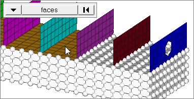
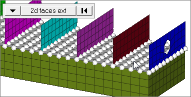
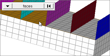
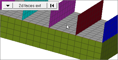
face angle / individual selection |
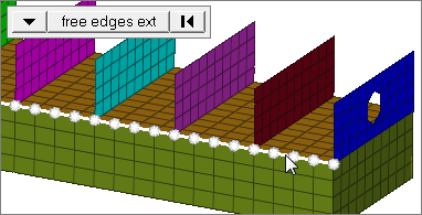
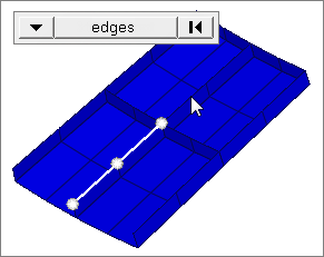
Face angleThe face angle is the angle between the normal of facets that share an element edge. A facet can either be a shell element itself, or one of the faces of a solid element. The normal of triangular facets is that of the plane defined three corner vertices. Whereas, the normal of quadrilateral facets is calculated by taking the cross-product between its two diagonals. This special treatment for quadrilaterals is because a warped shape does not lie completely on a plane. Only available when the entity selector is set to nodes or elems and the selection mode is set to faces, 2d faces ext, free edges, free edges ext, edges, or edges ext. Individual SelectionSelect individual elements on a face or select individual free/shared edges of elements. Only available when the entity selector is set to nodes or elems and the selection mode is set to faces, free edges, or edges. |
||||||
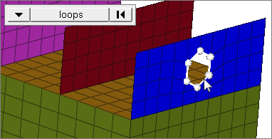
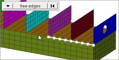
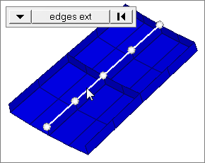
edge angle |
Splits edges that belong to a given face. When the edge angle is 180 degrees, edges are the continuous boundaries of faces. For smaller values, these same boundary edges are split wherever the angle between segments exceeds the specified value. A segment is the edge of a single element. Only available when the entity selector is set to nodes and the selection mode is set to free edges, free edges ext, edges, or edges ext. |
The following action buttons appear:
Button |
Action |
||
translate + |
Translate the selection in the positive direction. For example, when translating nodes along the x-axis this would move each selected node to a higher X coordinate value.
|
||
translate - |
Translates the selection in a negative direction. For example, a node at X,Y,Z coordinates (50,33,42) translated along the global x-axis with a magnitude of 5 would move to (45,33,42). |
||
reject |
Reverts the last translation. Only the most recent translation can be rejected; to undo multiple translations, simply translate in the opposite direction. Each positive translation can be undone by a negative translation of the same magnitude and direction. |
||
return |
Completes the translation and exits the Translate panel.
|
Notes
|
You may encounter the following error messages when trying to perform an invalid translation function. Use the information included here to solve the problem.
| • | N3 should not be selected for a direct move from N1 to N2. |
When using the magnitude = N2-N1 option, you cannot use N3 to define the direction of translation; the direction is wholly defined by N1 and N2.
| • | N1N2N3 and vector options do not utilize local coordinate system information. |
When using either one of these options for the plane selector, set the coordinate system to global system.