Mesh Overview
A mesh is a discretised representation of a geometry model or mesh model. The geometry model (or mesh model) is meshed to obtain a simulation mesh which is given as input to the Solver to calculate the requests. The accuracy of the results depends greatly on generating a mesh that is an accurate representation of the model.
For preliminary simulations of your model, you are recommended to use a coarse mesh to obtain initial and fast results that can be used as a rough verification (although the results may be inaccurate). As a next step, you should do mesh convergence tests1 before taking the simulated results as truly final and accurate.
The following terminology is used:
- Geometry part / Model geometry
- Geometry part or model geometry refers to the computer-aided design (CAD) in the model. The CAD could be created in CADFEKO or imported from a wide range of CAD formats.
- Mesh part / Model mesh
- The mesh part or model mesh is similar to CAD parts, but the mesh parts are models created from mesh elements, not CAD. The mesh is created either in CADFEKO (by unlinking from meshed CAD or creating mesh elements directly) or importing a mesh.
- Simulation mesh
- The simulation mesh refers to the final mesh used by the Solver. CAD always has to be meshed. Models created from mesh parts can either be remeshed to create a simulation mesh, or they can be used without being remeshed. The simulation mesh is then the same as the model mesh.

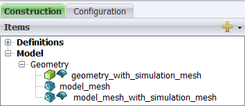
Figure 1. Example of (1) a geometry part that was meshed and has a simulation mesh, (2) a mesh part without a simulation mesh (still needs to be meshed) and (3) a mesh part that has a simulation mesh.
- The
 icon indicates a mesh part or model mesh.
 - The
 icon indicates that a mesh instance has already been created or defined. This mesh
instance is used when simulating the model.