Creating a Mesh (Segments, Triangles, Tetrahedra)
Discretisise the model into segments, triangles and tetrahedra (where applicable).
The solver method affects whether triangles or tetrahedra is created when meshing the model.
-
Open the Create mesh dialog using one of the
following workflows:
- On the Mesh tab, in the
Meshing group, click the
 Create mesh icon.
 - Press Ctrl+M to use the keyboard shortcut.

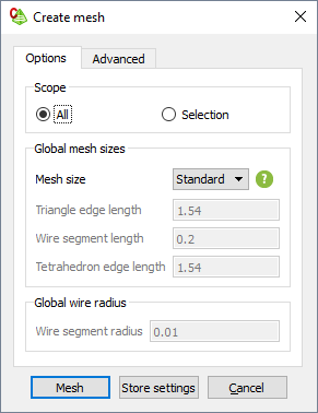
Figure 1. The Create mesh dialog (Options tab). - On the Mesh tab, in the
Meshing group, click the
-
Specify the parts to be meshed.
- To mesh the full model, under Scope, click All.
- To mesh only the selected part of the model, under Scope, click Selection. Select the parts in the model tree or the 3D view before starting the meshing process.
-
Specify the mesh size.
- To create a mesh using automatic mesh sizes, in the Mesh size field, from the drop-down list select Coarse, Standard or Fine.
- To create a mesh with a custom mesh size, in the Mesh
size field, from the drop-down list
select Custom. Specify the lengths applicable to the
model.
- In the Triangle edge length field, specify the triangle edge length.
- In the Wire segment length field, specify the wire edge length.
- In the Tetrahedron segment length field, specify the tetrahedron edge length.
-
In the Wire segment radius field, specify the global
wire radius.
Note: A local mesh refinement takes precedence over global mesh settings.
-
Click Create to create the mesh and to close the
dialog. A summary indicating the number of mesh elements are logged in the
message window.
Once the mesh settings have been verified on the Create mesh dialog, you can press Ctrl+Shift+M to perform the mesh without dialogs or prompts.