Define Cell
When this panel is opened, the cell is automatically created according to the geometry previously generated, see Geometry Menu.
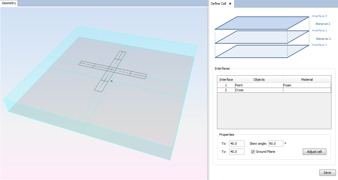
Figure 1. Define Cell panel
This panel has the following considerations:
- An interface is generated for every different Z coordinate that is detected on the geometry. In the image, the cell has two interfaces because a point and the plane are defined on two different XY planes with different Z order.
- According to the scheme on the top of the panel, the interfaces and materials are numerated from the lowest Z coordinate to the highest one. In the image 'Interface 1' correspond with the interface where the point is defined and 'Material 1' that is 'Foam' corresponds with the blue layer. On the top, 'Interface 3' corresponds with the interface where the plane is defined.
- The material layers, that defines the material located over the interface of the same number, are only represented while this panel is opened.
Parameters:
- In the table the user can assign defined materials to the layers, except to the upper interface that is the top of the cell. To add a material to de materials database for use it for a layer see Materials Menu (Periodical Structures Module).
- Cell dimension: Tx and Ty determines the x-size and the y-size of the cell.
- Skew angle: Define the angle of displacement for the y-axis to the replication cells. Normally, a skew angle of 45 to 90 degrees is defined. The upper cells will move to the right on the y-axis.
- Ground Plane: The check box define a reflection (enabled) or transmission (disabled) cell. The ground plane is added automatically on the bottom interface, where a point must be presented or the present geometry will be removed. The ground plane will be painted on gray to visualize it when this panel is displayed.
- Adjust Cell: The button resize the cell to the bounding box geometry.