Travelling-Wave Array
This section explains how to create a travelling-wave slot array antenna (non-resonant) fed by a rectangular waveguide.
When the option is selected, the next panel and a previsualization of the antenna with the parameters on the panel are displayed.
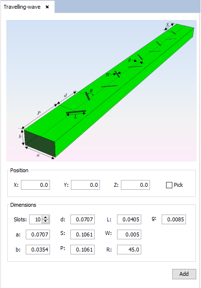
Figure 1. Travelling-wave Array panel
- Position: set the Cartesian coordinates for the position of the antenna. For the antenna, user can select the position with the mouse by selecting the 'Pick' check box and clicking any point in the geometry panel.
- Dimensions: set the values of the number of slots (Slots), the width and height of the feeding waveguide (a and b), the distance between adjacent slots (d), the length and width of the slots (L and W), the rotation angle of the slots (R in degrees), the distance from the start of the waveguide to the first slot center (P), the distance from the end of the waveguide to the last slot center (S) and the separation from the slot center to the broadwall center of the waveguide (g).
For each modification on parameters panel, this previsualization will be updated for the new parameters.
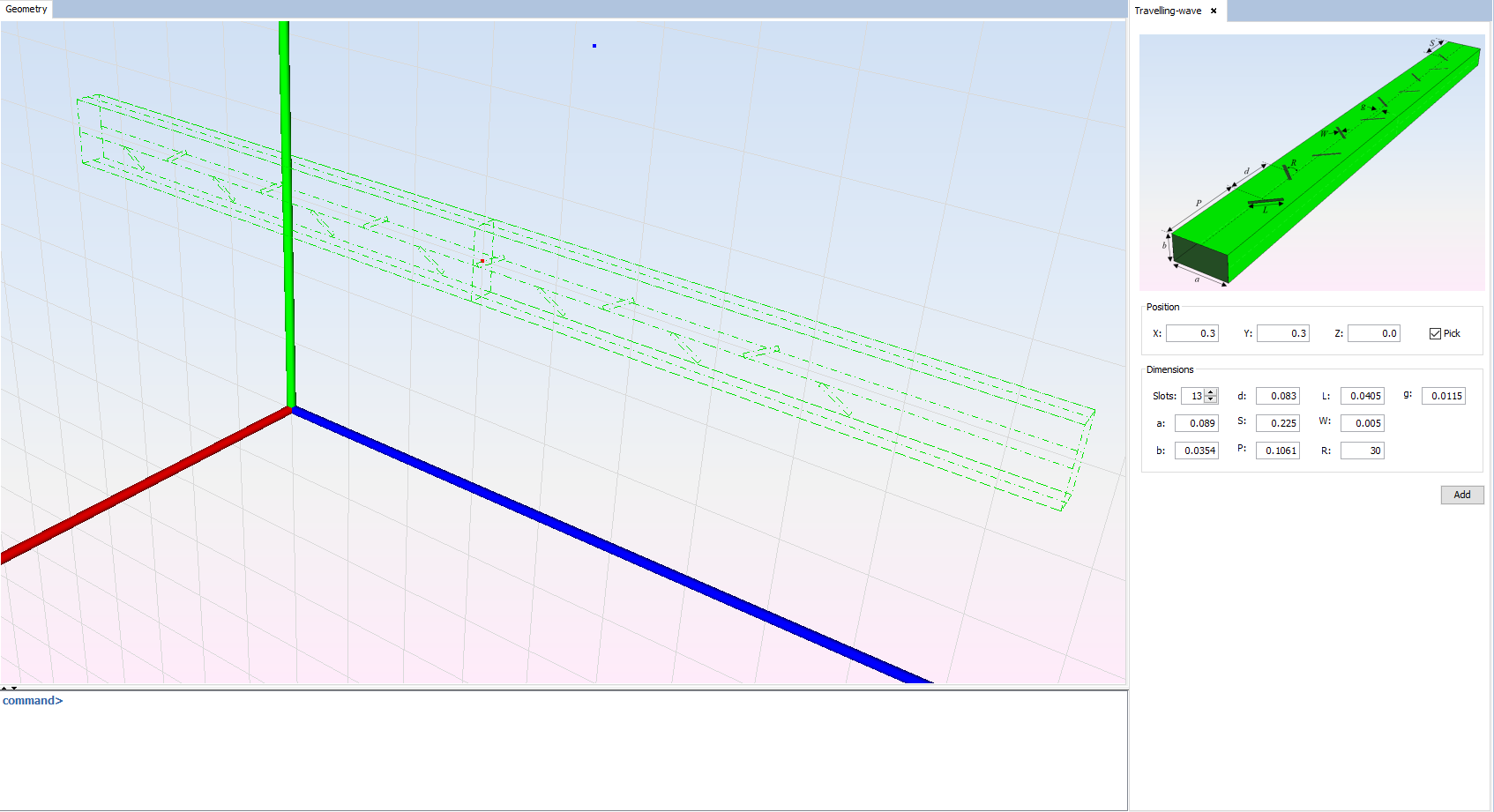
Figure 2. Travelling-wave Array previsualization
Clicking on 'Add' button, the final visualization for the antenna with red filled waveguide ports (input and output) will be shown.
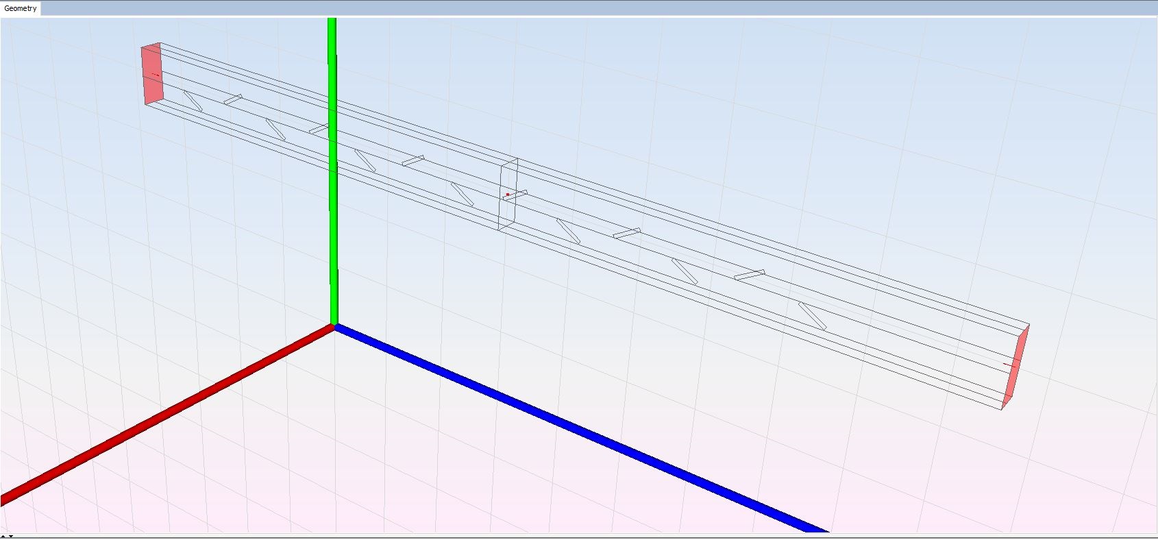
Figure 3. Travelling-wave Array visualization