Data files are available in the tutorial_models folder in the
installation directory in Program Files\Altair\2021\InspireExtrudePolymer2021.2\tutorial_models\extrudepolymer\tutorial-2\.
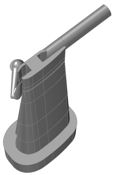
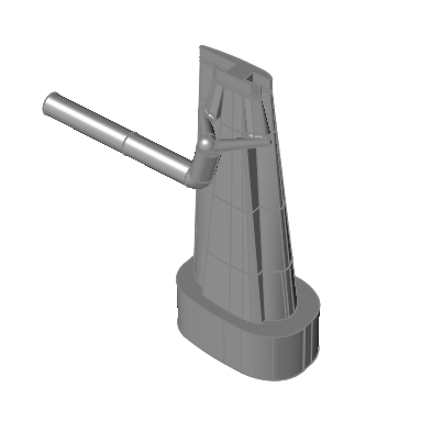
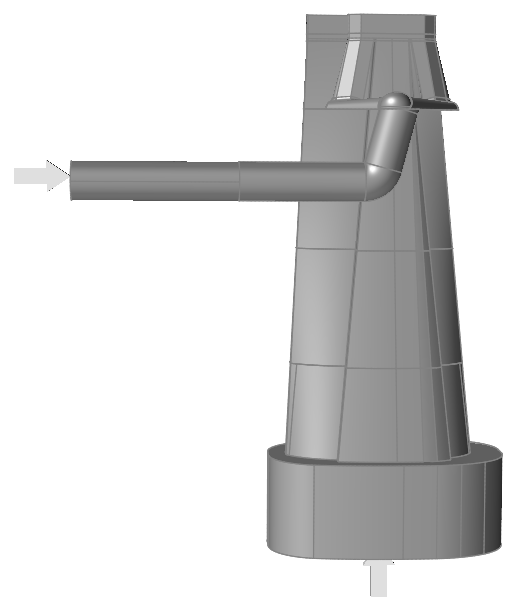
Open the bodysidemoldTool.x_t tutorial model file from the file menu or by
dragging and dropping the file into the Inspire Extrude window.
Note: In this tutorial, the die geometry includes a feeder and die cap. The CAD
file can be in parasolid, step, or part file format.
The model should appear in the Inspire Extrude window.
Orient the Model
Click the Extrusion ribbon.
Click the Orient icon.
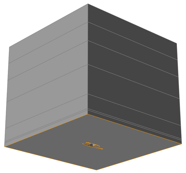
On the model, click the exit surface.
The model is oriented such that the profile is on the run-out table
surface, which is at Y=0, and the profile extrudes in the +Z
direction.
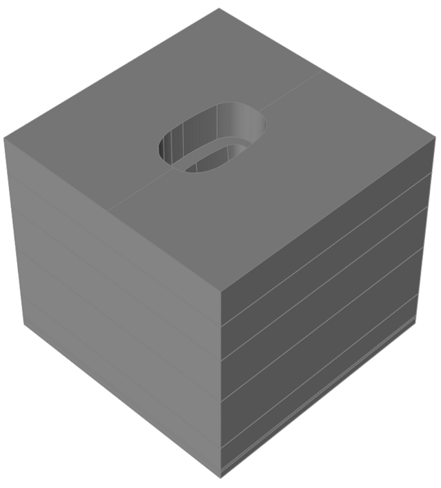
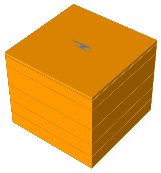
Extract Flow Volume
Click the Polymers ribbon.
Click the Flow Volume icon.
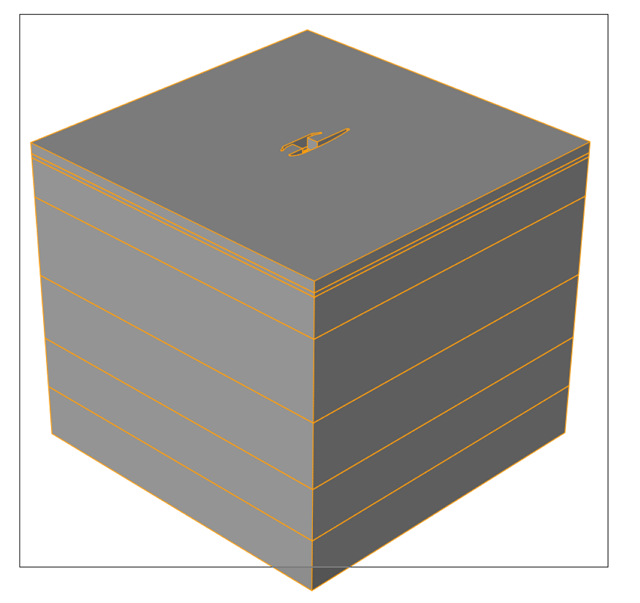
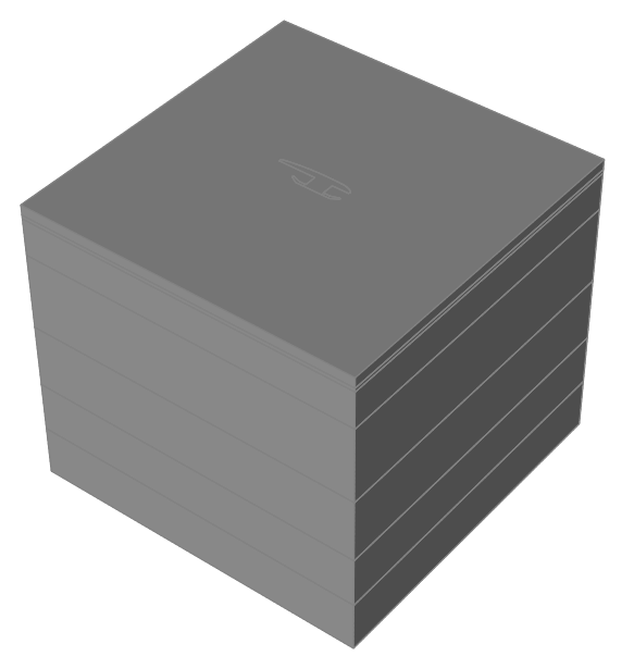
Click and drag the cursor over the entire model to create a box, then
release.
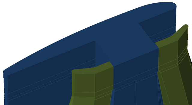
Delete Unwanted Solids
Press A to show all solids.
Press and hold CRTL and select flow die solids.
Press H to hide the selected solids.
Optional: Verify the names of Extract Solids. To start, open the model browser by
pressing F2. This model's extracted flow solids are
renamed as Plate1, Plate2, Plate3, Plate4, Plate5, and Plate6.
Note: If a die plate has more than one void, then each of the extracted solids
will have the same name. In this example, there are two components named
Plate4 and two named Plate5.
Note: You can perform this check to ensure that future progress will proceed as
shown in this tutorial.
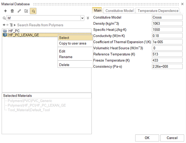
Select Materials
This die is a coextrusion die, so you will need to select two polymers for this
situation. Those polymers are:
EXXON_PAXON_AB50_003
HF_PC_LEXAN_GE
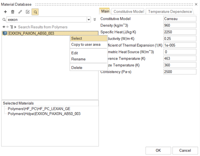
Click the Materials icon.
Select Polymers > HF_PC > HF_PC_LEXAN_GE
Right click on the material and click Select.
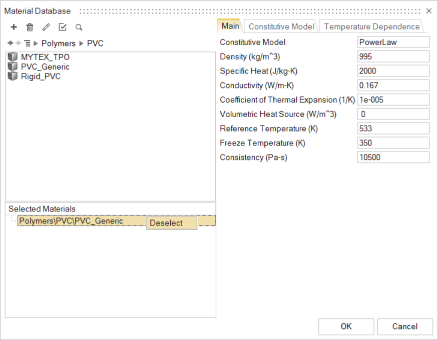
After the material is selected, verify the bottom material under
Selected Materials and deselect the materials that
are not the two needed for this analysis.
Note: To deselect a material, right click on the selected material and click
Deselect.
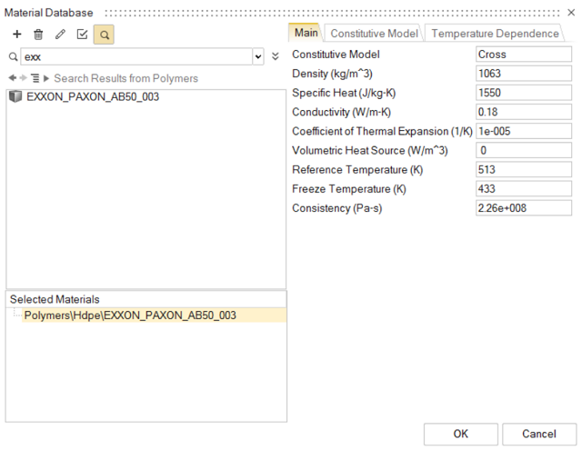
Repeat the above steps to select the EXXON_PAXON_AB50_003 material.
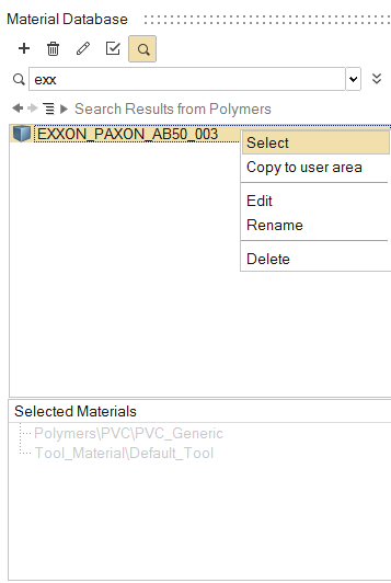
Optional: Another way to search for your materials is to click in the Search
Box in the Materials Window.
Click in the Search Box.
Type the name of the alloy.
Right click on the alloy name and select it.
Specify Process Data: Inlets
Click the Inlet icon.
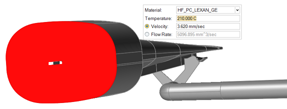
Zoom in to the first Inlet Region of the Polymer Melt.
Select the first inlet face. Specify the inlet conditions:
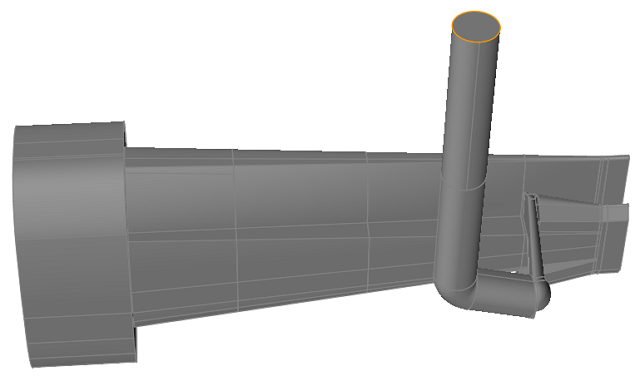
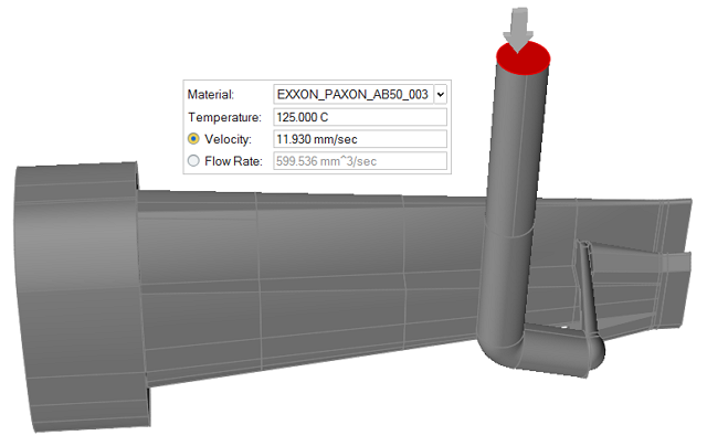
Zoom in to the second Inlet Region of the Polymer Melt.
Select the second Inlet face. Specify the inlet conditions:
Right-click and mouse through the check mark to exit, or double-right-click.
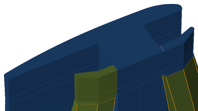
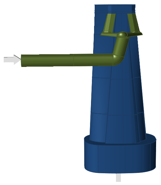
Organize Solids Into Polymer Layers
Click the Organize icon.
Inspire Extrude will then automatically organize all the
displayed flow solids into polymers layers based on the previously specified
inlet conditions.
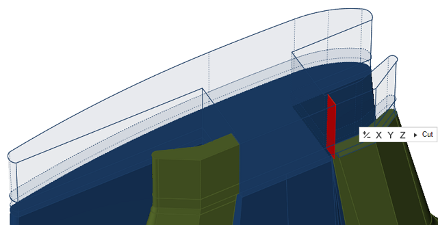
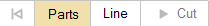
Cut Land
Click the Cut Land icon.
Click Parts and select the parts of the model with partitioning
lines.
Click Line and select the partitioning line.
Click Cut and perform the trimming operation.
Follow all the steps from the previous, but commit them to the other
partitioning line.
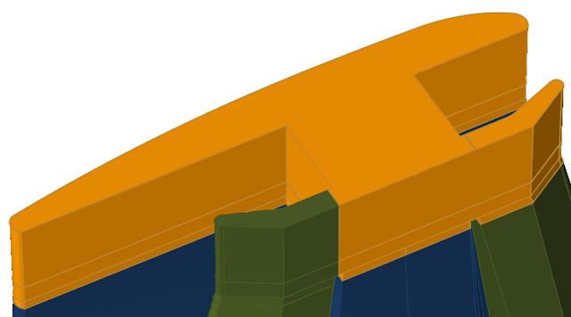
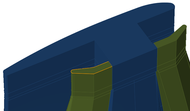
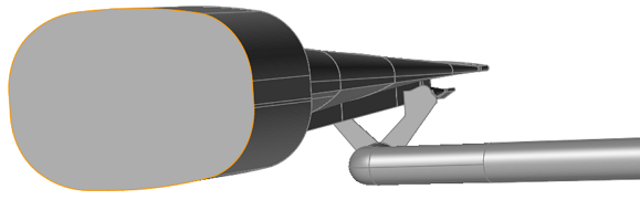
Create Profile Solids
Click the Profile icon.
Zoom in to the land region and select the land exit surface as shown.
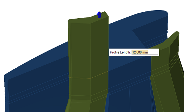
Inspire Extrude will create a Profile solid
and use 3 times the length of the Land as default. You can change this if
needed. We recommend the profile solid length be 3-4 times the actual land
region. In this model, use 12 mm for the profile length.
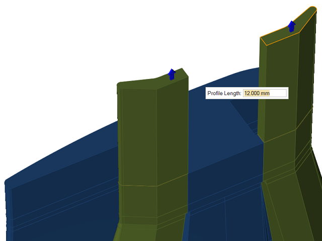
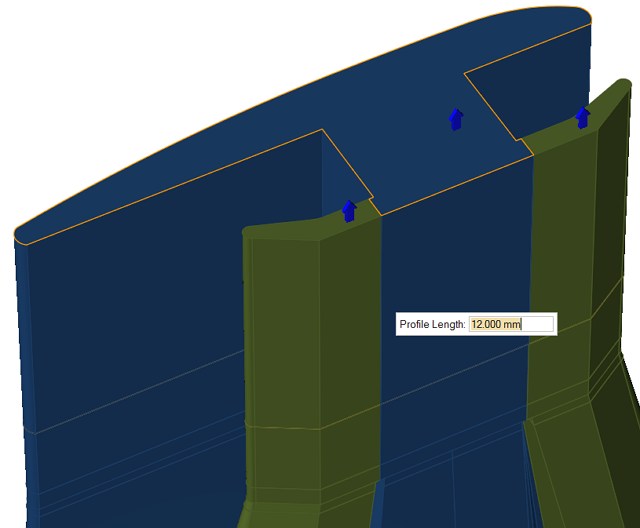
Repeat the above steps if you have multiple exits. This model has 3 exits, the
rest of which are shown below.
Save Model
Click File > Save As... to save the model.
Note: We suggest you save this new model in a location that is different than
the original tutorial model's location to prevent any future conflict with
those files.
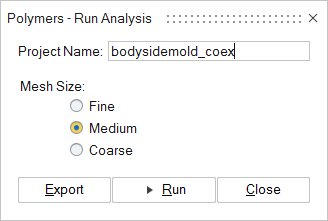
Submit the Job for Simulation
Click the Analysis icon.
Specify the parameters of the analysis process.
Click Run.
Monitor Job Status
Once the results are ready, you should see a green flag notifying you that the
results are ready for visualization. Click that green flag to view the
results.
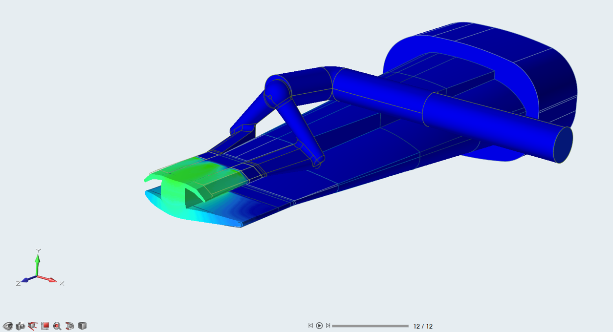
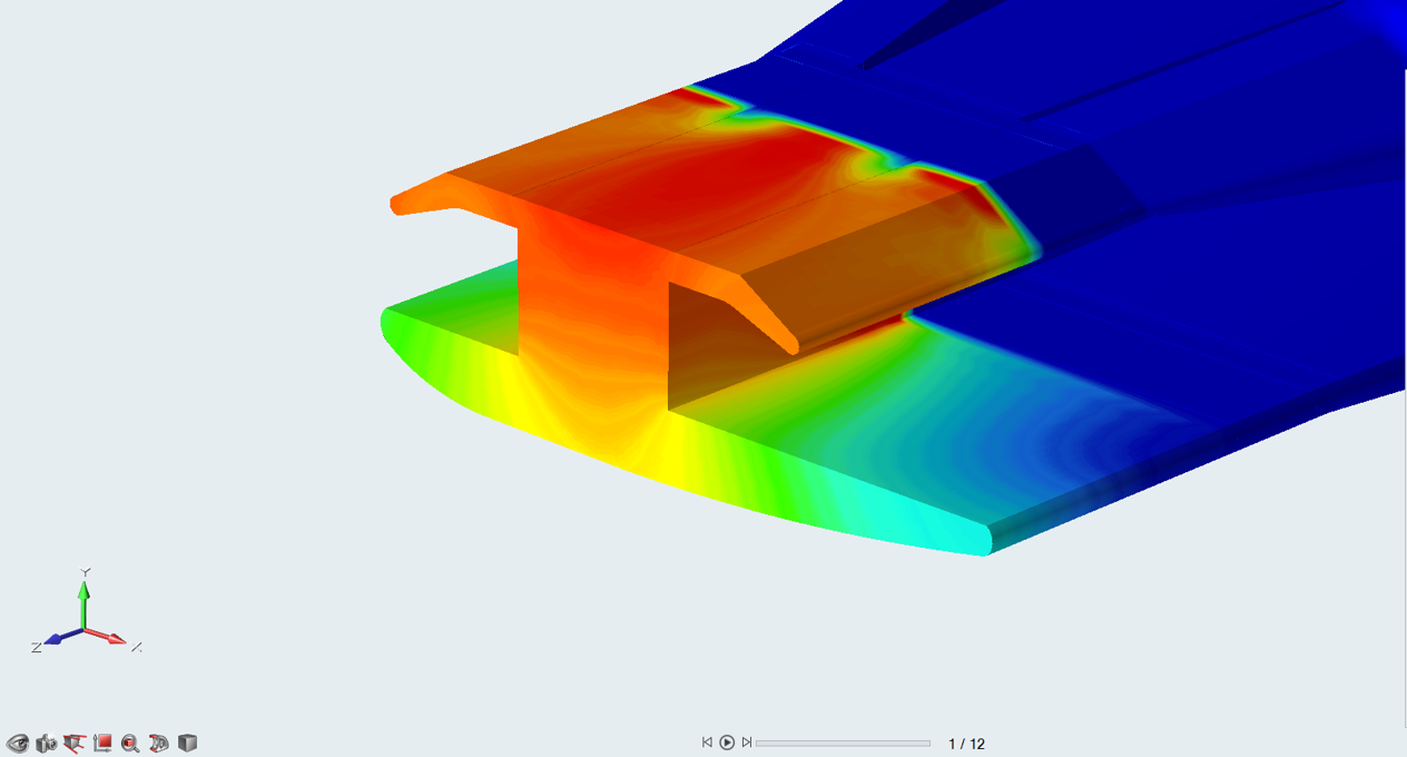
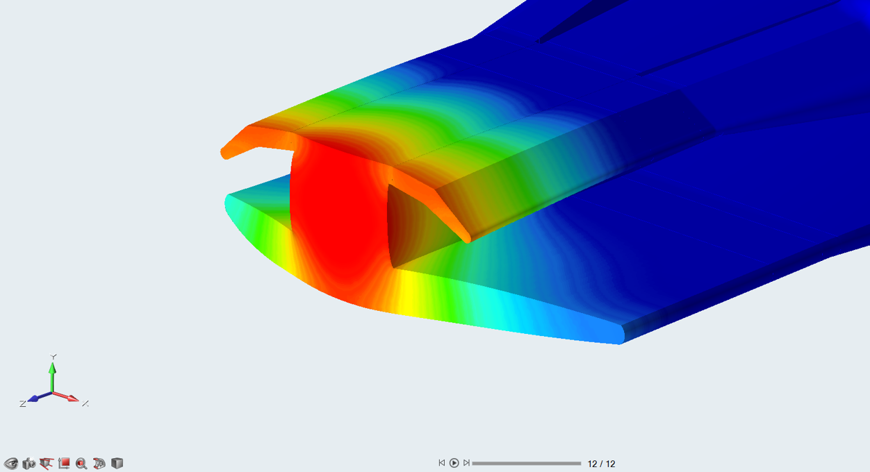
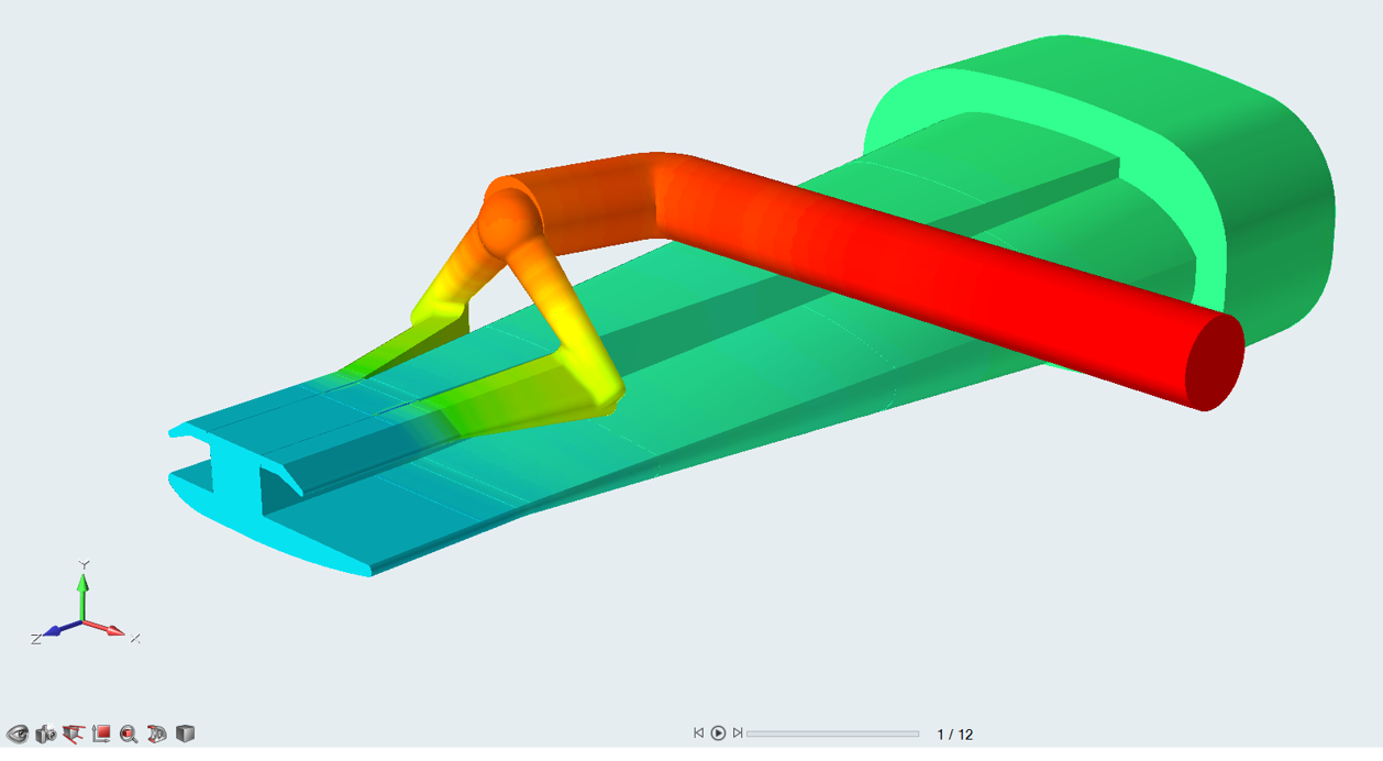
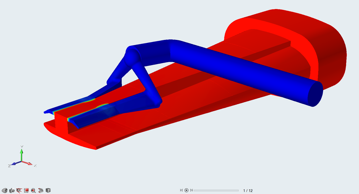
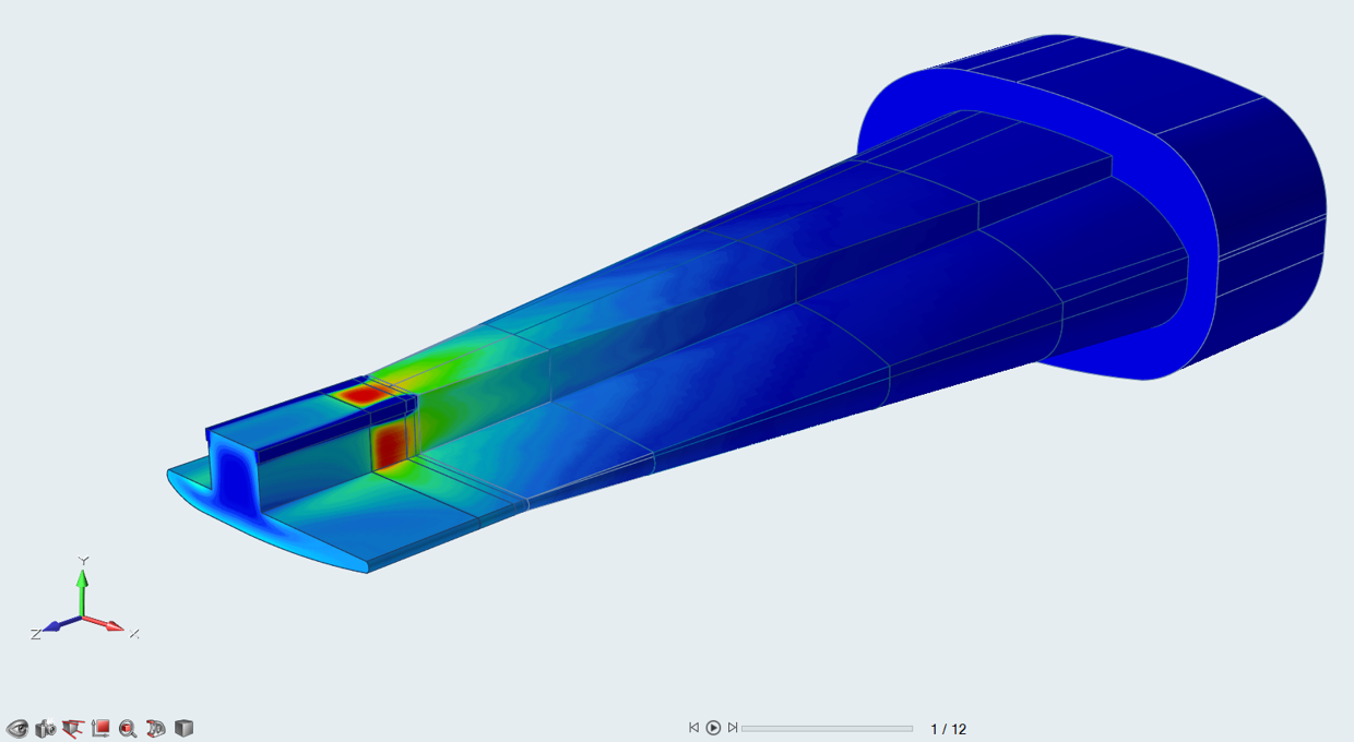
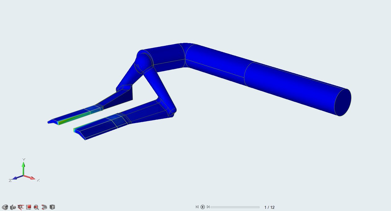
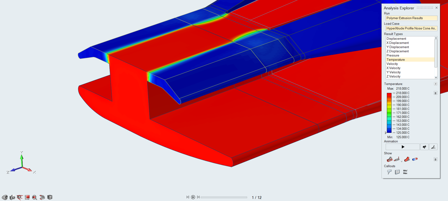
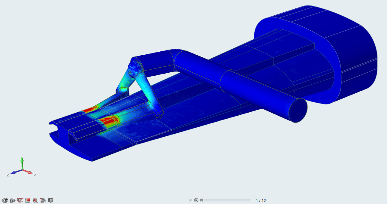
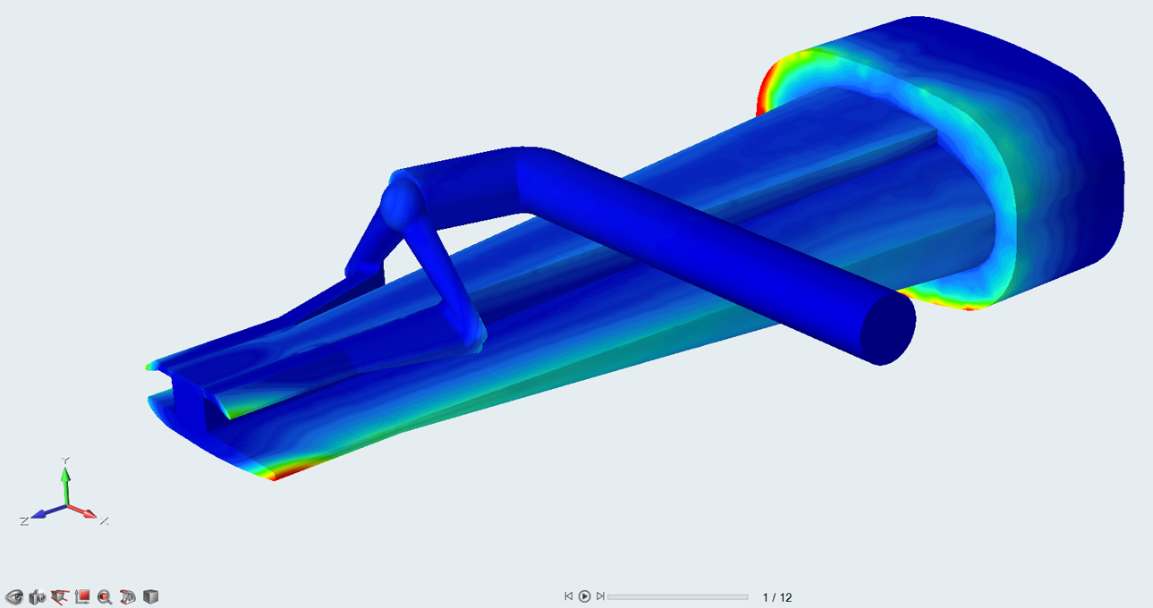
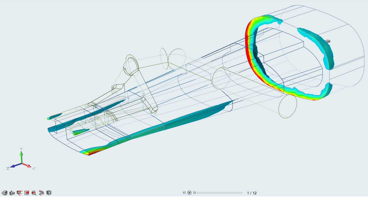
View Simulation Results
Review simulation results in the Analysis
Explorer.
Figure 1. Velocity Figure 2. Velocity - Die Exit Figure 3. Deformation Figure 4. Pressure Figure 5. Temperature Figure 6. Temperature - Polymer Layer 1 Figure 7. Temperature - Polymer Layer 2 Figure 8. Temperature - Die Exit Figure 9. Strain Rate Figure 10. Residence Time Figure 11. Residence Time


 and select the partitioning line.
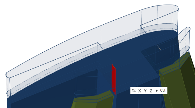
 and perform the trimming operation.