Tutorial: Setup a Symmetric Model
Prepare a symmetric model for various forms of simulation.
There are several angles of symmetric models for simulation.
- 10°
- 30°
- 45°
- 90°
- 180° - You will need an extra step to set this angle up.
Note: Other than the 180° sector model, there are no special settings required to
simulate the sector of the full model.
For the 180° sector model, you need at least one edge or imprint on the billet solid
crossing the billet center.
To detect half symmetry, the internal automatic boundary conditions
capture module needs a node at the center (X=0, Y=0) of the
billet that is touching the dummy-block.
The minimum of one edge/imprint on the billet is needed because the center node in
the figure will only be created when there is that edge/imprint on the
billet.
There is no node near X=0, Y=0 because there is no edge/imprint at the billet
center.
Note: When there is an edge near the billet center, the batch mesher
automatically creates a node at the billet center.
Import/Process Die Geometry
-
After a complete setup, trim the full model in the indicated area.
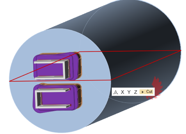
-
Delete unwanted solids and bearing curves.
- Organize solids as Billet, Feeder, Portholes, Pocket1, etc., as it was modeled previously.
- Organize lines belonging to the bearing curve as BearingCurve.
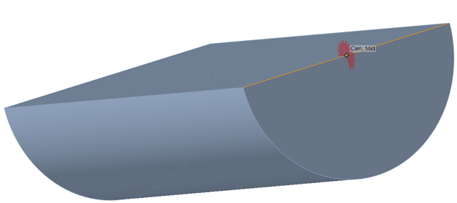
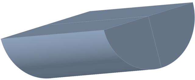
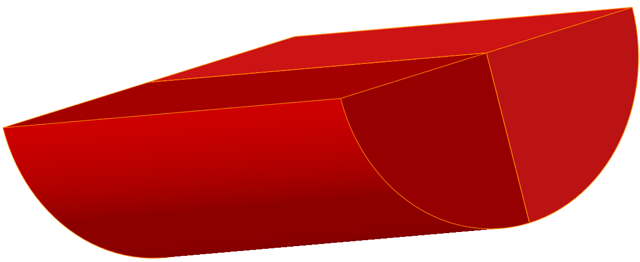
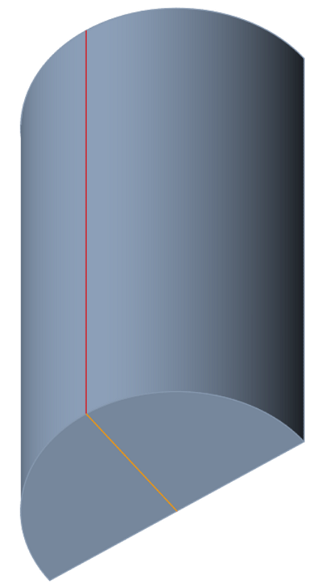
Trim Billet Solids at Billet Center
- Isolate the Billet solid.
-
Click on the Organize icon to trim the billet.

-
Move your mouse cursor to the center of the billet-dummy-block end and cut, as
shown in the figures.
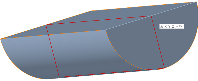
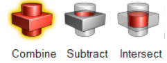
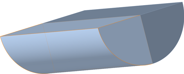
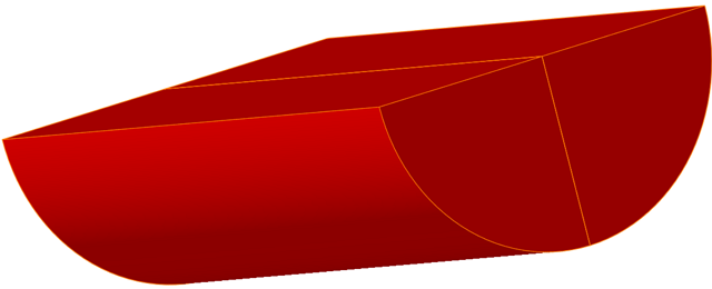
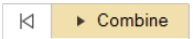
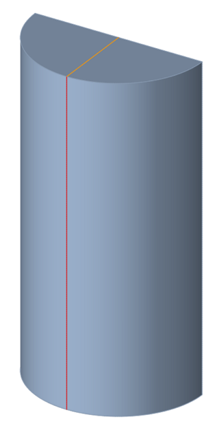
Combine Two Halves of Billet Solids
Once the billet solid is cut, use the Combine tool to
combine two halves of the billet, as shown in the figure.
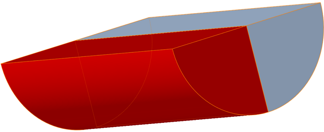
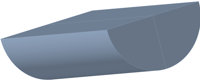
Remove Imprints with Simplify
-
Click the Simplify icon.
-
Click the Imprints icon.

-
Select the edges on the billet to remove the 3 imprints on the solid, leaving
the imprint on the long, flat side untouched.
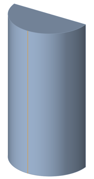
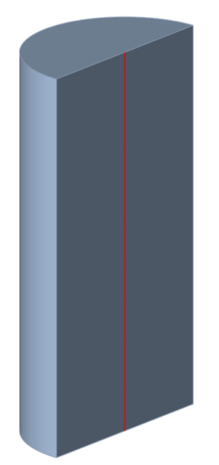
Note: Keep the imprint in the model as shown in the last figure.
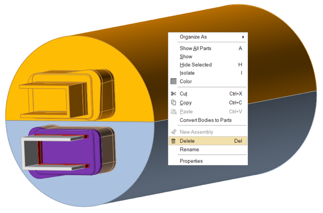
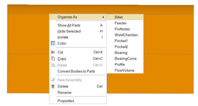
Organize the Billet Solid as Billet Again
- Click the Extrusion ribbon.
-
Select the Billet solid. Right-click and select .
- Proceed to the simulation.