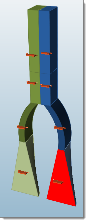
Creating Process Conditions
Use the Process Data tool to create process conditions for the model.
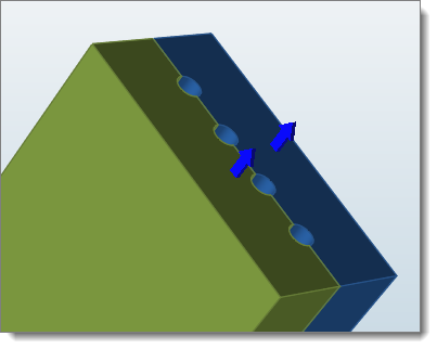
Creating the Exit Surfaces
Exits are where the material exits the domain. The model can have more than one exit surface, and should have at least one exit surface.
-
From the Polymers ribbon, Process Data tools, click the Exit
tool.

-
Select the exit surface for each layer to create the exit boundary
condition.
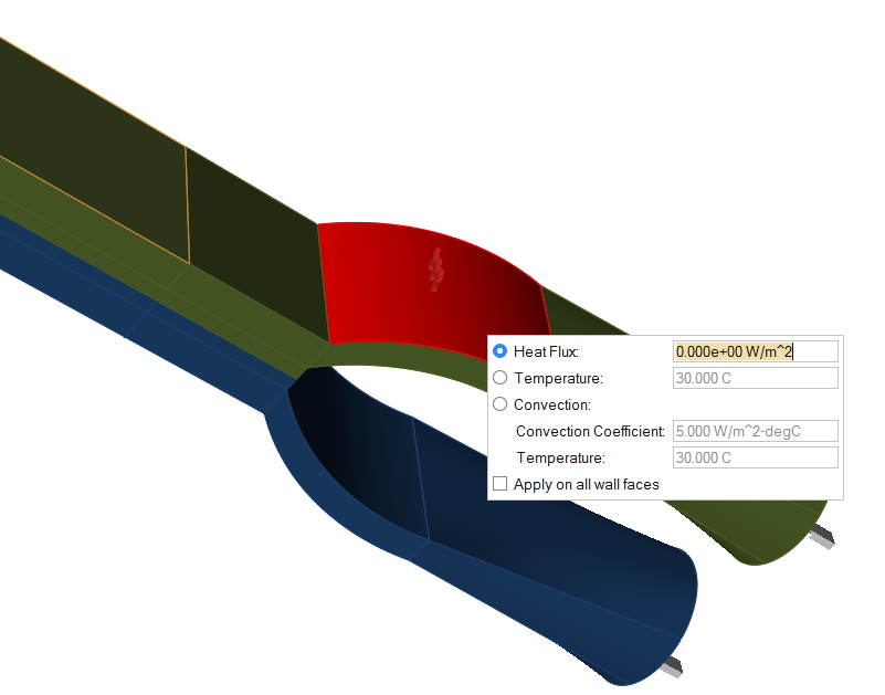
Creating the Wall Surfaces
Walls are used for specifying heat transfer condition.
-
From the Polymers ribbon, Process Data tools, click the Wall
tool.

-
Select the surface to apply the wall boundary conditions.
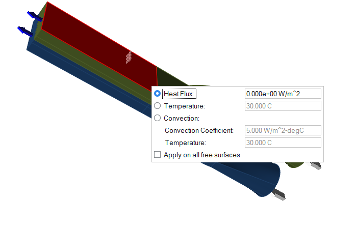
Creating the Free Surfaces
Specify heat transfer data on free surfaces exposed to ambient conditions.
-
From the Polymers ribbon, Process Data tools, click the Free Surface
tool.

-
Select the profile surface to apply the free surface boundary conditions.
Selecting the Symmetry Surfaces
Symmetry is used for specifying the symmetry planes.
-
If your model has symmetry, from the Polymers ribbon,
Process Data tools, click the
Symmetry tool.

-
Select the Symmetry surfaces.
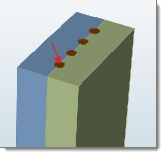
Selecting the Insert Part
If the extrusion has a metal insert, that condition is applied using insert parts. Inserts are modeled using BCs (the interface condition between insert and the polymer).
-
From the Polymers ribbon, Process Data tools, click the Insert
tool.

-
Select the insert part.
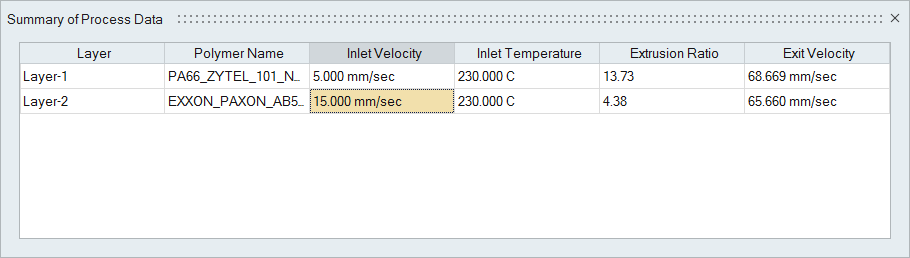
Adjusting Inlet Velocities to Achieve Uniform Exit Velocities
Polymer layers should have uniform exit velocities, which can be balanced by adjusting inlet velocities.
When extruding two or more polymers to create a coextruded part, the exit velocity and temperature conditions should be compatible. Exit velocities of all of the layers should be more or less the same. Temperatures of each layer need not be identical, as they have to be based on the material properties, but should coexist well. This tool will summarize the data to ensure it is compatible and will not affect the product quality and to help the user correct these issues if they arise.
-
From the Polymers ribbon, click the Process
Data Summary icon on the Process Data
tool.

The Summary of Process Data table is displayed.