OS-E: 0020 Inline-4 Engine Head
The structural analyses of a cylinder head under various loading conditions can be accomplished by means of finite element analysis using OptiStruct. The results, combined with each analysis concerning the different operating processes of the engine, can be separated mainly into two parts.
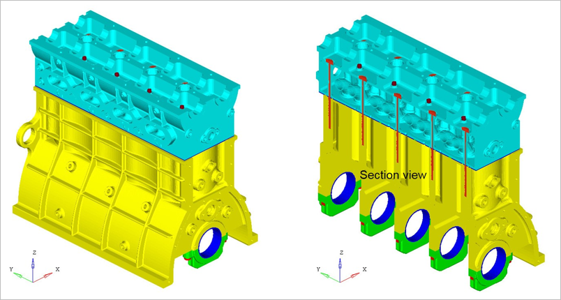
Figure 1. FE Model
The capacity of gasket sealing mainly depends upon the pre-stressing of the bolts, which are the source of the maximum external loading on the inner structure of the cylinder head.
The location of the weakest contact pressure on the raised portion of the gasket can be transferred as a result of the effect of thermal stress or strain, which may cause the increase in pressure and escaping of the gas.
Model Files
Refer to Access the Model Files to download the required model file(s).
The model file used in this example includes:
NLSTAT_ALTAIR_PWT.zip
Model Description
- FE Model
- Element Types
- CHEXA
- MAT1
- Young’s Modulus
- 21500 MPA
- Poisson's Ratio
- 0.3
- MGASK
- Direct Tensile Modulus
- 0.001
- Transverse Shear Modulus
- 12000
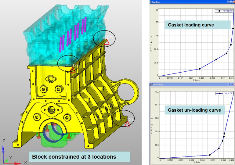
Figure 2. Details of the Boundary Condition and Gasket Material Loading and Unloading Curve
- Assembly Loadings
The major percentage of the loading applied to the engine is the assembly loading. This mainly refers to the pre-stressing of the bolts, and it plays an important role in preventing gas from escaping from the internal part of the engine.
- Thermal LoadingsIn the case of thermal loadings, the nodal temperatures resulting from the prescribed thermal analysis are assigned to all corresponding nodes of the FEM model of the second cylinder head in order to calculate the thermal stress/strain of the cylinder head structure.
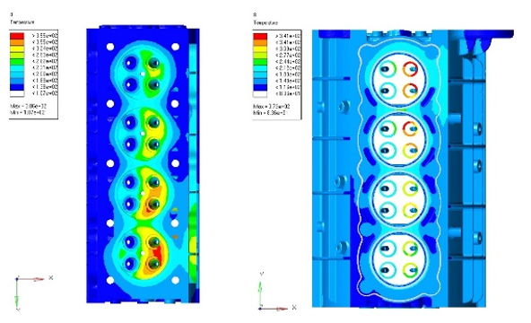
Figure 3. Gas pressure
The gas pressure created as a result of the firing of the spark plug is imposed on the surface of the combustion chamber. However, the magnitude of the gas pressure varies with different durations of the cycle. For the steady-state analysis, the average gas pressure is introduced into the loading conditions for the simulation here.
- Case 1
- Assembly Loadings
- Applied pretension loading (41.25 KN) in head bolts
- Case 2
- Thermal Loadings
- Lock pretension displacements
- Case 3
- Gas Pressure
- Lock pretension displacements
Results
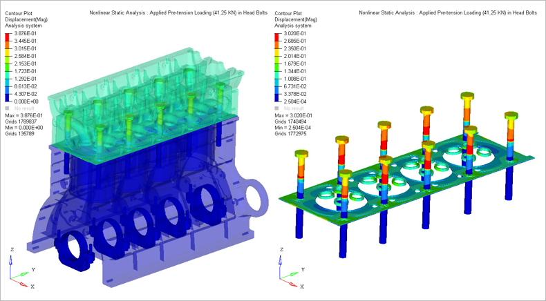
Figure 4. Subcase 1: Displacement Contour
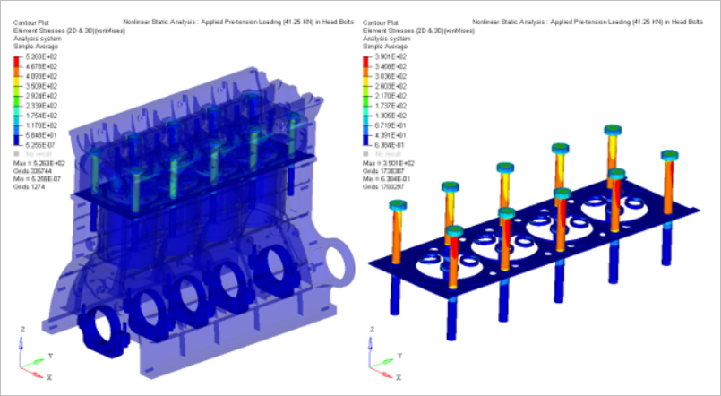
Figure 5. Subcase 1: Stress Contour

Figure 6. Subcase 1: Gasket Pressure and Sealing Status
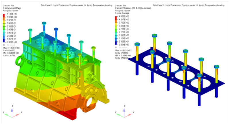
Figure 7. Subcase 2: Displacement and Stress Contour
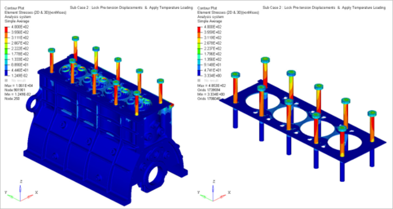
Figure 8. Subcase 2: Stress Contour
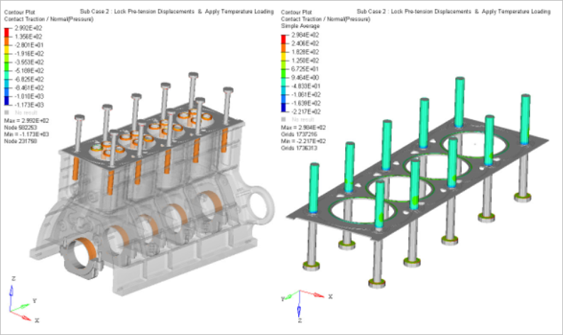
Figure 9. Subcase 2: Contact Pressure Contour

Figure 10. Subcase 3: Displacement Contour
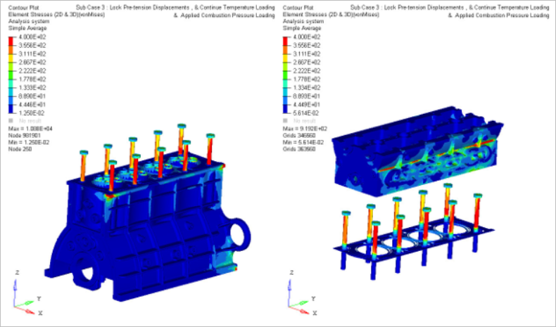
Figure 11. Subcase 3: Stress Contour
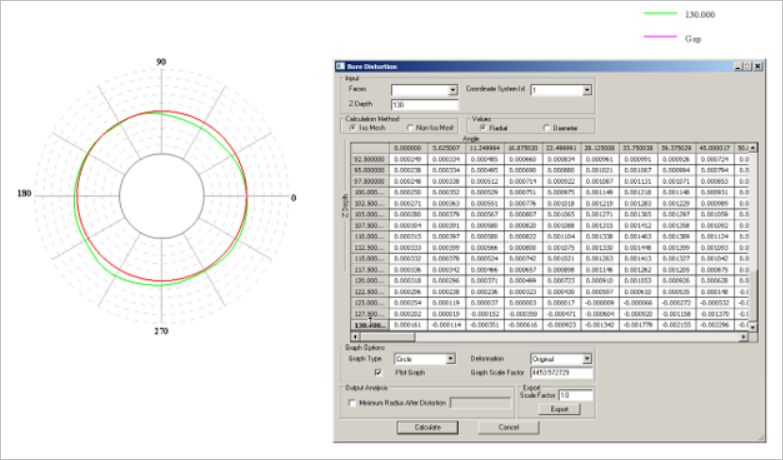
Figure 12. Subcase 3: Bore Distortion Graph of 4th Cylinder (Calculation Using SimLab)