OS-T: 5020 3D Bracket Model using the Free-shape Method
In this tutorial you will perform a shape optimization on a solid bracket model using the Free Shape optimization method. The objective of this optimization is to reduce the stress by changing the geometry of the bracket model.
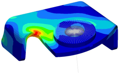
Figure 1.
- Objective
- Minimize (Max von Mises Stress).
- Constraints
- No Constraints.
- Design Variables
- Grids move normal to the surface.
Launch HyperMesh and Set the OptiStruct User Profile
Open the Model
Set Up the Optimization
Create Free-shape Design Variables
-
Using the nodes selector, select the nodes shown in Figure 2. Sselect only the face nodes that are also on
shells.
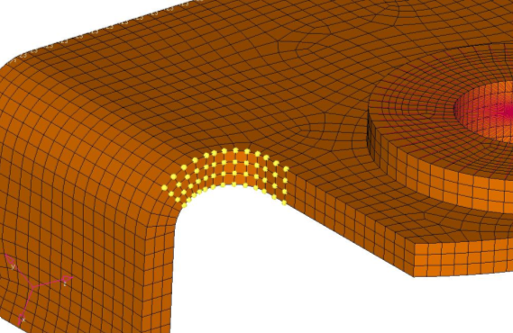
Figure 2. Free-shape Design Space
Create Optimization Responses
- From the Analysis page, click optimization.
- Click Responses.
-
Create a static stress response.
- In the response= field, enter Stress.
- Set the response type to static stress.
- Using the props selector, select stress_faces.
- Set the response selector to von mises.
- Under von mises, select both surfaces.
- Click create.
- Click return to go back to the Optimization panel.
Define the Objective Function
-
Create an objective reference.
-
Define the objective.
- Click the objective panel.
- Select minmax.
- Using the dobjrefs= selector, select MAX_STR.
- Click create.
- Click return to go back to the Optimization panel.
Define the SHAPE Card
- From the Analysis page, click the control cards panel.
- In the Card Image dialog, click SHAPE.
- Set FORMAT to H3D.
- Set TYPE to ALL.
- Set OPTION to ALL.
- Click return twice to go back to the main menu.
Run the Optimization
View the Results
View the Shape Results
-
In the top, right of the application, use the navigations buttons to navigate
to the Design History (page 2).
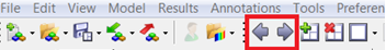
Figure 3. -
In the Results Browser, select the last iteration
(Iteration 8).
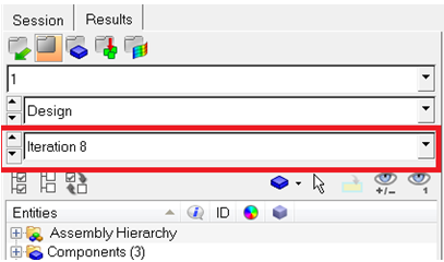
Figure 4. -
On the Results toolbar, click
 to open the Deformed panel.
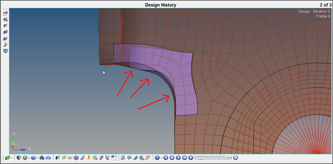
Figure 5.
View a Contour Plot of the Stress
-
In the top, right of the application, use the navigations buttons to navigate
to the Subcase 1 - step (page 3).
Figure 6. -
In the Results Browser, select the last iteration
(iteration 8).
Figure 7. -
On the Results toolbar, click
 to open the Contour panel.
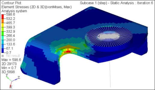
Figure 8.
Set Up a New Free-shape Optimization Simulation with Moving Constraints
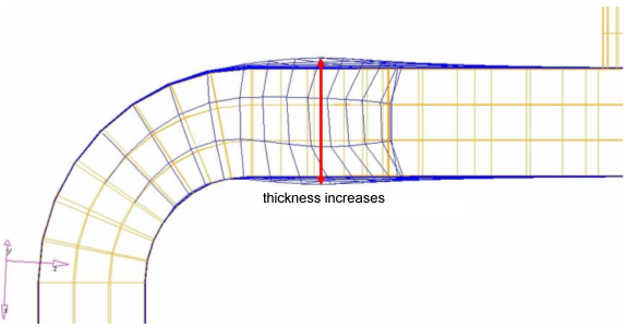
Figure 9. Free-shape Results Without Constraints
In practice, however, there will be some sort of constraints imposed upon the movement of grids due to manufacturability. For this tutorial model, thickness must be unchanged to avoid any interference with other parts.
In this step you will define constraints on DSHAPE grids such that the thickness of design space will remain unchanged.
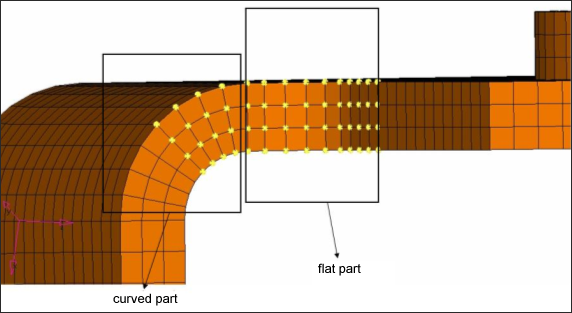
Figure 10. Design Space On Curved And Flat Part
The constraints on the curved part will be created using a local rectangular coordinate system (the other constraints on the flat part do not need a local coordinate system). Therefore, a local rectangular coordinate system (z-axis will point to normal to DSHAPE surface) needs to be created first.
-
In the top, right of the application, click
 /
/ to
move back to Page 1 and the HyperMesh client.
to
move back to Page 1 and the HyperMesh client.
-
Define a local coordinate system.
- From the 1D page, click the systems panel.
- Select the create by axis direction subpanel.
- Click , then enter 20999 in the id= field.
- Click origin and enter 20999 in the id= field.
- Click x-axis and enter 15989 in the id= field.
- Click xy-plane and enter 19462 in the id= field.
- Click create.
- Click return.
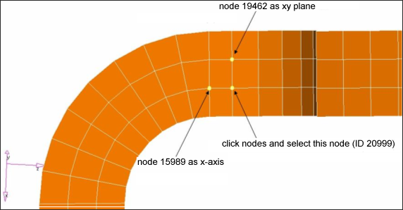
Figure 11. Local Coordinate System -
Create constraints on the flat part without any coordinate system.
-
Using the nodes selector, select the nodes shown in Figure 12.
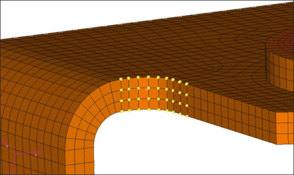
Figure 12. Constraints On Free Shape Design Space -
Using the N1, N2, and N3 selectors, select the three nodes on plane
geometry.
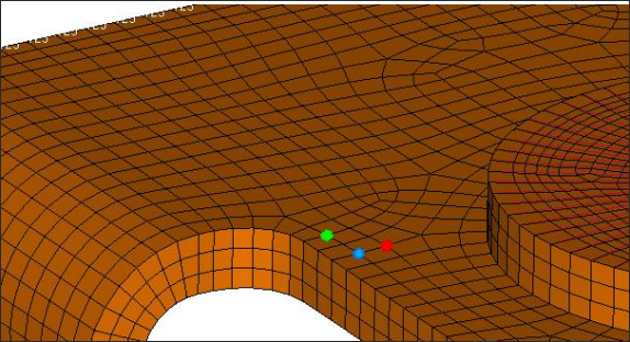
Figure 13. Three Nodes To Defined The Plane
These nodes will move only on the specified plane. -
Using the nodes selector, select the nodes shown in Figure 12.
-
Create constraints on the curved part using a local coordinate system.
-
Using the nodes selector, select the nodes shown in Figure 14.
Only select the nodes that are on the curved part.
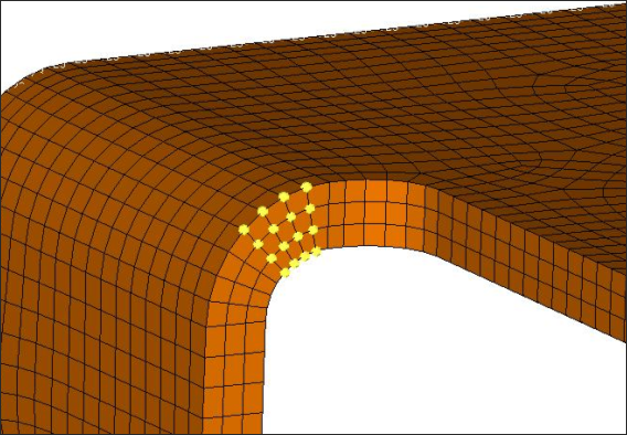
Figure 14. Constraints On Free-shape Design Space On Curved Part
-
Using the nodes selector, select the nodes shown in Figure 14.
Run the Optimization
View the Results
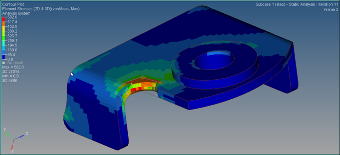
Figure 15.