The Altair GUI Toolkit is a resource tool for coding Tcl/Tk dialogs. It contains documentation of the HyperWorks commands, demo pages that illustrate our Altair GUI standards, and sample code for creating those examples.
The Model Identification Tool, known as HyperWorks, is a profile in HyperGraph for fitting test data from frequency- and amplitude-dependent bushings to analytical models. The HyperWorks operates in conjunction with HyperGraph, MotionView and MotionSolve to provide you with a comprehensive solution for modeling and analysis.
The Altair Bushing Model is a library of sophisticated, frequency- and amplitude-dependent bushing models that you can use for
accurate vehicle dynamics, durability and NVH simulations. The Altair Bushing Model supports both rubber bushings and hydromounts.
This section provides information about using the Altair Bushing Model, also known as AutoBushFD, with MotionView. The Altair Bushing Model is a sophisticated model that you can use to simulate the behavior of bushings in vehicle
dynamics, durability and NVH simulations.
The Model Identification Tool (MotionView) is a utility in HyperGraph that you use to fit experimental data to various bushing models. The MotionView generates a General Bushing System file, .gbs file, which defines the bushing properties.
You can add an Altair Bushing Model, also known as AutoBushFD, a frequency-dependent bushing, to your MotionView model using the Add Auto Entity tool in MotionView.
In addition to adding a single bushing to your project, you can also add a pair of bushings such as AutoBushFD pair.
When you add a pair, MotionView automatically reflects modifications you make on the left bushing of the pair to the right bushing, unless you choose
otherwise. MotionView assumes bilateral symmetry about the global X-Z plane.
HgTrans translates solver results files from their native file format to Altair Binary Format (ABF). This can be done using
the HgTrans GUI or via the HgTrans batch mode.
The HyperWorks Automation Toolkit (HWAT) is a collection of functions and widgets that allows an application to quickly assemble
HyperWorks automations with minimal effort and maximum portability.
The Model Identification Tool, known as HyperWorks, is a profile in HyperGraph for fitting test data from frequency- and amplitude-dependent bushings to analytical models. The HyperWorks operates in conjunction with HyperGraph, MotionView and MotionSolve to provide you with a comprehensive solution for modeling and analysis.
This section provides information about using the Altair Bushing Model, also known as AutoBushFD, with MotionView. The Altair Bushing Model is a sophisticated model that you can use to simulate the behavior of bushings in vehicle
dynamics, durability and NVH simulations.
This section describes how you attach a bushing to a model.
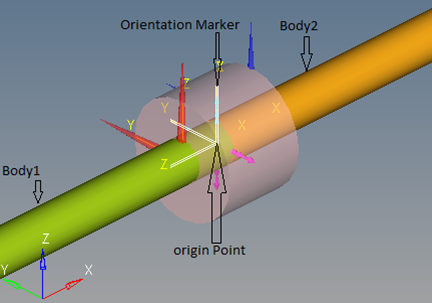
Use the Collector buttons on the panel to select the two bodies the bushing connects,
the marker that orients the bushing, and the point that locates the bushing.
From the Model Browser in MotionView, select the entity
AutoBushFD.
A panel opens with the bushing information displayed. It includes a
Connectivity pane and a Properties pane.
Click Body 1 and Body 2 to select
a body from the modeling window, or double-click to
select a body from the browser dialog.
Click Marker to select a marker from the modeling window, or double-click to select a marker from the
browser dialog. Markers for the X, Y, and Z axes define the bushing’s X, Y, and
Z axes.
Click Point 1 to select a point from the modeling window or double-click to select a point from the
browser dialog. The point’s location defines the bushing’s location.