PERIODIC_BOUNDARY_CONDITION
Specifies general periodic boundary conditions on pairs of nodes.
Type
AcuSolve Command
Syntax
PERIODIC_BOUNDARY_CONDITION("name") {parameters...}
Qualifier
User-given name.
Parameters
- variable or var (enumerated) [=all]
- Periodic boundary condition variable.
- all
- All variables. May be used only with periodic, axisymmetric and two_reference_frames types.
- velocity or vel
- Velocity vector.
- pressure or pres
- Pressure.
- temperature or temp
- Temperature.
- eddy_viscosity or eddy
- Turbulence kinematic eddy viscosity.
- kinetic_energy or tke
- Turbulence kinetic energy.
- eddy_frequency or tomega
- Turbulence eddy frequency.
- dissipation_rate
- Turbulence dissipation rate.
- intermittency
- Transition intermittency.
- transition_re_theta
- Transition Re-Theta.
- species_1 or spec1
- Species 1.
- species_2 or spec2
- Species 2.
- species_3 or spec3
- Species 3.
- species_4 or spec4
- Species 4.
- species_5 or spec5
- Species 5.
- species_6 or spec6
- Species 6.
- species_7 or spec7
- Species 7.
- species_8 or spec8
- Species 8.
- species_9 or spec9
- Species 9.
- viscoelastic_stress or vest
- Viscoelastic stresses.
- field
- Volume fraction of field in multi field for levelset and algebraic Eulerian problems or mass fraction of field in multi field for the humid air model.
- mesh_displacement or mesh_disp
- Mesh displacement vector.
- precedence (integer) [=1]
- Precedence of this boundary condition set with respect to other sets. The set with the highest value has precedence.
- type (enumerated) [=periodic]
- Type of the periodic boundary condition.
- periodic or zero
- Simple periodic condition.
- axisymmetric
- Axisymmetric condition. Requires rotation_axis.
- two_reference_frames
- Interface condition between two regions with different reference frames. Requires rotation_force_1 and rotation_force_2. Obsolete parameter.
- constant_offset
- Periodic condition with a constant offset. Requires constant_value for scalar variables and constant_values for vector variables.
- nodal_pair_offset
- Periodic condition with offset given on a nodal-pair basis. Requires nodal_pair_values.
- user_function_offset
- Periodic condition with offset given by a user-defined function. Requires user_function, user_values and user_strings.
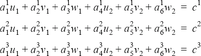
- constant_coefficients
- General two-node constraint with constant coefficients. Requires constant_values.
- nodal_pair_coefficients
- General two-node constraint with coefficients given on a nodal-pair basis. Requires nodal_pair_values.
- user_function_coefficients
- General two-node constraint with coefficients given by a user-defined function. Requires user_function, user_values and user_strings.
- single_unknown_offset
- Periodic condition with a single unknown offset.
- single_unknown_ratio
- Periodic condition with a single unknown ratio.
- nodal_pairs or pairs (array) [no default]
- List of nodal point pairs in this set.
- rotation_axis or axis (array) [={0,0,0;0,0,1}]
- Axis of rotation. Used with axisymmetric type.
- rotation_force_1 or rot_1 (string) [=none]
- User-given name of the rotational force command of the first set of nodes. If none, stationary frame of reference is assumed. Used with two_reference_frames type. Obsolete parameter.
- rotation_force_2 or rot_2 (string) [=none]
- User-given name of the rotational force command of the second set of nodes. If none, stationary frame of reference is assumed. Used with two_reference_frames type. Obsolete parameter.
- constant_value or value (real) [=0]
- Constant value of offset. Used with constant_offset type for scalar variables.
- constant_values or values (array) [={0,0,0}]
- Constant values of offset or the constant coefficients. Used with constant_offset type for vector variables and with constant_coefficients type.
- field (string) [no default]
- Value of the periodic boundary condition for field. Used with variable field.
- nodal_pair_values (array) [no default]
- Constraint values for nodal-pairs. Used with nodal_pair_offset and nodal_pair_coefficients types.
- user_function or user (string) [no default]
- Name of the user-defined function. Used with user_function_offset and user_function_coefficients types.
- user_values (array) [={}]
- Array of values to be passed to the user-defined function. Used with user_function_offset and user_function_coefficients types.
- user_strings (list) [={}]
- Array of strings to be passed to the user-defined function. Used with user_function_offset and user_function_coefficients types.
- multiplier_function (string) [=none]
- User-given name of the multiplier function for scaling the offset values of the periodic boundary condition. If none, no scaling is performed.
- active_type (enumerated) [=all]
- Type of the active flag. Determines which nodal pairs in this set will have this periodic
boundary condition imposed.
- all
- All nodal pairs in this set are active.
- none
- No nodal pair in this set are active.
- user_function or user
- User-defined function. Requires active_user_function, active_user_values and active_user_strings.
- active_user_function (string) [no default]
- Name of the user-defined function for the active flag. Used with user_function active type.
- active_user_values (array) [={}]
- Array of values to be passed to the active flag user-defined function. Used with user_function active type.
- active_user_strings (list) [={}]
- Array of strings to be passed to the active flag user-defined function. Used with user_function active type.
Description
PERIODIC_BOUNDARY_CONDITION( "inflow/outflow periodicity" ) {
   variable     = all
   type         = periodic
   nodal_pairs  = { 1, 101, 201 ;
                    2, 102, 202 ;
                    3, 103, 203 ; }
}
defines a simple periodic boundary condition on all solution fields of the problem. This command specifies that the solution at node 101 is equal to that of node 201, and similarly that the solution of node 102 is equal to that of node 202, and so on.
The variable parameter specifies the solution field to which the periodic boundary condition applies. If the problem does not solve for such a variable, the periodic boundary condition is ignored. See the STAGGER command. The all variable may be used to specify periodic boundary condition on all variables in the problem. This variable is only allowed with types periodic, axisymmetric, and two_reference_frames. A periodic boundary condition on a scalar variable, such as temperature, defines a single constraint. However, for vector variables, such as velocity, a periodic boundary condition imposes three constraints, typically in the x, y, and z directions.
The nodal_pairs parameter is a three-column array corresponding to a unique, within this set, nodal-pair number, and node one and two of the pair, one pair per row. The node numbers must be valid numbers, as given by the COORDINATE command. AcuSolve properly handles duplicate node pairs and nodes periodic with themselves.
1      101          201
2      102          202
2 103 203PERIODIC_BOUNDARY_CONDITION( "inflow/outflow periodicity" ) {
variable = all
type = periodic
nodal_pairs = Read( "inflow-outflow.pbc" )
}For a given variable, a given node may be included in more than one periodic boundary condition pair. In this case, enough periodic conditions must be supplied to uniquely specify the entire condition set. These conditions may be imposed via a single or multiple PERIODIC_BOUNDARY_CONDITION commands. For example, nodal pairs (1,2) and (3,4) may have simple periodic conditions, and nodal pairs (1,3) and (2,4) have axisymmetric conditions, with the same axis of rotation. Note that this is an over-specification of constraints (but consistent).
Any potential inconsistency in multiply-specified periodic boundary conditions on a given node is resolved through precedence. The constraints with higher values of precedence take precedence over constraints with lower values. For constraints with the same precedence value, the periodic boundary condition sets specified later take precedence over the ones specified earlier. In all cases, nodal boundary conditions take precedence over periodic boundary conditions.
A periodic type periodic boundary condition specifies that the values of a variable on two nodes are equal, as in the above example. In case of a vector variable, each component of the vector on the two nodes are equal.
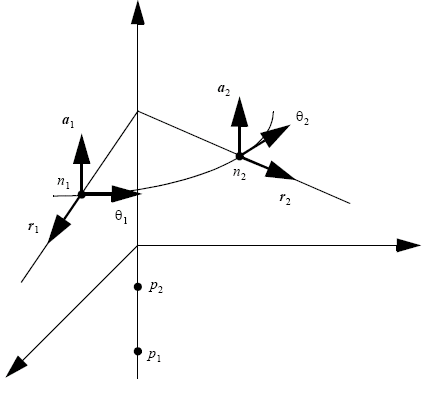
Figure 1. Axisymmetric Condition on a Vector Field
PERIODIC_BOUNDARY_CONDITION( "a pie cut axisymmetric constraint" ) {
   variable      = all
   type          = axisymmetric
   nodal_pairs   = { 1, 1, 2 ; 2, 11, 12 ; 3, 21, 22 ; }
   rotation_axis = { 0, 0, 0 ; 0, 0, 1 ; }
}
defines an axis of rotation in the global z-direction. The rotated velocity vectors of nodes 1 and 2 are equal. Similar conditions apply to nodal pairs (11,12) and (21,22). For a scalar variable the axisymmetric periodic boundary condition type is equivalent to the periodic type.
COORDINATE {
   coordinates      = { 1, 1.,
                        0., 0. ;
                       11, 1., 0., 0. ; # same as node 1
                       ... }
}
ROTATION_FORCE( "rotating frame" ) {
   centrifugal       = on
   coriolis          = on
   center            = { 0, 0, 0 }
   angular_velocity  = { 0, 1, 0 }
}
BODY_FORCE( "my body force" ) {
   rotation_force    = "rotating frame"
}
ELEMENT_SET( "fluid in rotating frame of reference" ) {
   elements          = { 1, 1, 2, 3, 4 ;
                         ... }
   body_force        = "my body force"
   ...
   }
ELEMENT_SET( "fluid in stationary frame of reference" ) {
   elements          = { 1, 11, 45, 46, 47 ;
                         ... }
   body_force        = none
   ...
}
PERIODIC_BOUNDARY_CONDITION( "interface between two frames of reference" ) {
   variable          = all
   type              = two_reference_frames
   nodal_pairs       = { 1, 1, 11 ;
                         ... }
   rotation_force_1  = "rotating frame"
   rotation_force_2  = none
}
Nodes one and 11 have the same nodal coordinates. Node one is referenced by the element set "fluid in rotating frame of reference" which is in a rotating frame of reference given by "rotating frame"; and node 11 is referenced by the element set "fluid in stationary frame of reference" which is stationary. The given two_reference_frames periodic boundary condition specifies that the velocities of nodes 1 and 11 transformed to the global stationary frame of reference are equal.

For all other variables, the two_reference_frames periodic boundary condition reduces to the simple equality condition. If n > 2 regions with different frames of reference intersect at a point or an edge, one set of nodes for each region is needed and at least n - 1 conditions must be specified. Depending on the particular problem, there are typically several geometrical constraints on the relationship between the parameters of the reference frames and the surface separating the element sets associated with each reference frame. For instance, the velocity at x due to the reference frame motion itself, the second term on each side in the equation above, may need to be parallel to this surface. Since these constraints are not general, AcuSolve cannot check for them and so the responsibility for ensuring geometric compatibility between reference frames falls to you.
PERIODIC_BOUNDARY_CONDITION( "inflow/outflow pressure drop" ) {
   variable       = pressure
   type           = constant_offset
   nodal_pairs    = { 1, 101, 201 ; 2, 102, 202 ; 3, 103, 203 ; }
   constant_value = 2
}
PERIODIC_BOUNDARY_CONDITION( "accelerated velocity" ) {
   variable         = velocity
   type             = constant_offset
   nodal_pairs      = { 1, 15, 16 ; 2, 25, 26 ; }
   constant_values  = { 1, 0, 0 }
}PERIODIC_BOUNDARY_CONDITION( "interface between two frames of reference" ) {
variable = velocity
type = constant_pair_offset
nodal_pairs = { 1, 1, 11 ; ... }
nodal_pairs_values = { 1, 0, 0, 1 ; ... }
}This example implements the two_reference_frames periodic boundary condition example given above. The nodal_pair_values parameter is a multi-column array, corresponding to the nodal-pair number and the offset values. For a scalar variable this array has two columns and for a vector variable it has four columns.
1 0 0 1
...PERIODIC_BOUNDARY_CONDITION( "interface between two frames of reference" ) {
variable = velocity
type = constant_pair_offset
nodal_pairs = { 1, 1, 11 ; ... }
nodal_pairs_values = Read( "two-frame.pbc.val" )
}A periodic boundary condition of user_function_offset type may be used to model more complex behaviors; see the AcuSolve User-Defined Functions Manual for a detailed description of user-defined functions.
PERIODIC_BOUNDARY_CONDITION( "UDF BC for two frames of reference" ) {
   variable       = velocity
   type           = user_function_offset
   nodal_pairs    = { 1, 1, 11 ; ... }
   user_function  = "usrPbcOffsetExample"
   user_values    = { 0, 0, 0,  # rotating center
                      1 0, 1, 0,  # angular velocity
                      1 0, 0, 0,  # rotating center
                      2 0, 0, 0 } # angular velocity 2
}#include "acusim.h"
#include "udf.h"
UDF_PROTOTYPE( usrPbcOffsetExample ) ; /* function prototype */
Void usrPbcOffsetExample (
UdfHd udfHd, /* Opaque handle for accessing data */
Real* outVec, /* Output vector */
Integer nItems, /* Number of PBC pairs */
Integer vecDim /* = 3 */
) {
Integer pair ; /* a nodal pair counter */
Real xOrg1 ; /* x-center 1 */
Real yOrg1 ; /* y-center 1 */
Real zOrg1 ; /* z-center 1 */
Real xOmega1 ; /* x-angular velocity 1 */
Real yOmega1 ; /* y-angular velocity 1 */
Real zOmega1 ; /* z-angular velocity 1 */
Real xOrg2 ; /* x-center 2 */
Real yOrg2 ; /* y-center 2 */
Real zOrg2 ; /* z-center 2 */
Real xOmega2 ; /* x-angular velocity 2 */
Real yOmega2 ; /* y-angular velocity 2 */
Real zOmega2 ; /* z-angular velocity 2 */
Real xOff ; /* reduced x-offset */
Real yOff ; /* reduced y-offset */
Real zOff ; /* reduced z-offset */
Real xOmega ; /* reduced x-angular velocity */
Real yOmega ; /* reduced y-angular velocity */
Real zOmega ; /* reduced z-angular velocity */
Real * crd ; /* coordinates */
Real * usrVals ; /* user values */
Real * xCrd ; /* x-coordinates of node 1 */
Real * yCrd ; /* y-coordinates of node 1 */
Real * zCrd ; /* z-coordinates of node 1 */
Real * xOffset ; /* x-component of offset */
Real * yOffset ; /* y-component of offset */
Real * zOffset ; /* z-component of offset */
udfCheckNumUsrVals( udfHd, 12 ) ; /* check for error */
usrVals = udfGetUsrVals( udfHd ) ; /* get the user vals */
xOrg1 = usrVals[ 0] ; /* get x-center 1 */
yOrg1 = usrVals[ 1] ; /* get y-center 1 */
zOrg1 = usrVals[ 2] ; /* get z-center 1 */
xOmega1 = usrVals[ 3] ; /* get x-ang vel 1 */
yOmega1 = usrVals[ 4] ; /* get y-ang vel 1 */
zOmega1 = usrVals[ 5] ; /* get z-ang vel 1 */
xOrg2 = usrVals[ 6] ; /* get x-center 2 */
yOrg2 = usrVals[ 7] ; /* get y-center 2 */
zOrg2 = usrVals[ 8] ; /* get z-center 2 */
xOmega2 = usrVals[ 9] ; /* get x-ang vel 2 */
yOmega2 = usrVals[ 10] ; /* get y-ang vel 2 */
zOmega2 = usrVals[ 11] ; /* get z-ang vel 2 */
xOmega = xOmega2 - xOmega1 ; /* get reduced omega */
yOmega = yOmega2 - yOmega1 ; /* get reduced omega */
zOmega = zOmega2 - zOmega1 ; /* get reduced omega */
xOff = yOmega2 * zOrg2 - zOmega2 * yOrg2
- yOmega1 * zOrg1 + zOmega1 * yOrg1; /* get reduced offset */
yoff = zOmega2 * xOrg2 - xOmega2 * zOrg2
- zOmega1 * xOrg1 + xOmega1 * zOrg1; /* get reduced offset */
zoff = xOmega2 * yOrg2 - yOmega2 * xOrg2
- xOmega1 * yOrg1 + yOmega1 * xOrg1 /* get reduced offset */
crd = udfGetPbcCrd( udfHd ) ; /* get the coord. */
xCrd = &crd[0*nItems] ; /* localize x-coord. */
yCrd = &crd[1*nItems] ; /* localize y-coord. */
zCrd = &crd[2*nItems] ; /* localize z-coord. */
xOffset = &outVec[0*nItems] ; /* localize x-offset */
yOffset = &outVec[1*nItems] ; /* localize y-offset */
zOffset = &outVec[2*nItems] ; /* localize z-offset */
for ( pair = 0 ; pair < nItems ; pair++ ) {
xOffset[pair] = yOmega * zCrd[pair] - zOmega * yCrd[pair] - xOff ;
yOffset[pair] = zOmega * xCrd[pair] - xOmega * zCrd[pair] - yOff ;
zOffset[pair] = xOmega * yCrd[pair] - yOmega * xCrd[pair] - zOff ;
}
} /* end of usrPbcOffsetExample() */For a vector variable (as above) the dimension of the returned boundary condition vector, outVec, is the number of nodal pairs times three. For a scalar variable, it is the number of nodal pairs.
PERIODIC_BOUNDARY_CONDITION( "inflow/outflow scaled temperature profile" ) {
   variable        = temperature
   type            = constant_coefficients
   nodal_pairs     = { 1, 101, 201 ;
                       2, 102, 202 ;
                       3, 103, 203 ; }
   constant_values = { 2, -1, 0 }
}
PERIODIC_BOUNDARY_CONDITION( "a pie cut axisymmetric constraint" ) {
   variable          = velocity
   type              = nodal_pair_coefficients
   nodal_pairs       = { 1, 1, 2 ;
                         ... }
   nodal_pair_values = { 1,  0, 0,  1,  0,  0, -1,   0,  # z-axis
                         1,  1, 0,  1, -1,  0,  0,       # radial
                         1, -1, 0, -1, -1,  0,  0;       # tangential... }
}
The nodal_pair_values parameter is a multi-column array, corresponding to the nodal-pair number and the coefficient values. For a scalar variable this array has four columns and for a vector variable it has 22 columns. The nodal-pair values may be read from a file, as given in an example above.
A periodic boundary condition of user_function_coefficients type may be used to model more complex behaviors; see the AcuSolve User-Defined Functions Manual for a detailed description of user-defined functions.
PERIODIC_BOUNDARY_CONDITION( "UDF BC with fixed wall temperature" ) {
   variable       = temperature
   type           = user_function_coefficients
   nodal_pairs    = Read( "inflow-outflow.pbc" )
   user_function  = "usrPbcCoefExample"
   user_values    = { 0,    # fixed wall temperature
                     10,    # initial inflow bulk temperature
                      9,    # initial outflow bulk temperature
                   1005 }   # specific heat
   user_strings   = { "inflow surface", "outflow surface" }
}#include "acusim.h"
#include "udf.h"
UDF_PROTOTYPE( usrPbcOffsetExample ) ; /* function prototype*/
Void usrPbcOffsetExample (
UdfHd udfHd, /* Opaque handle for accessing data */
Real* outVec, /* Output vector */
Integer nItems, /* Number of PBC pairs */
Integer vecDim /* = 3 */
) {
Integer pair ; /* a running index */
Real wallTemp ; /* wall temperature */
Real inBulkTemp ; /* inflow bulk temperature */
Real outBulkTemp ; /* outflow bulk temperature */
Real cp ; /* specific heat */
Real inCoef ; /* inflow temp coefficient */
Real outCoef ; /* outflow temp coefficient */
Real cCoef ; /* constant coefficient */
Real * convFlux ; /* convective temperature flux */
Real * massFlux ; /* mass flux */
Real * usrVals ; /* user values */
Real * inCoefs ; /* return inflow temp coefficient */
Real * outCoefs ; /* return outflow temp coefficient */
Real * cCoefs ; /* return constant coefficient */
String* usrStrs ; /* user strings */
String inflowOsi ; /* inflow surface output */
String outflowOsi ; /* outflow surface output */
udfCheckNumUsrVals( udfHd, 4 ) ; /* check for error */
udfCheckNumUsrVals( udfHd, 2 ) ; /* check for error */
usrVals = udfGetUsrVals( udfHd ) ; /* get the user vals */
usrStrs = udfGetUsrStrs( udfHd ) ; /* get the user strs */
wallTemp = usrVals[0] ; /* get wall temp. */
inBulkTemp = usrVals[1] ; /* get inflow bulk T */
outBulkTemp = usrVals[2] ; /* get output bulk T */
cp = usrVals[3] ; /* get specific heat */
inflowOsi = usrStrs[0] ; /* get inflow surf. */
outflowOsi = usrStrs[1] ; /* get outflow surf. */
if ( !udfFirstStep(udfHd) ) { /* initial step? */
massFlux = udfGetOsiData( udfHd, inflowOsi, */
UDF_OSI_MASS_FLUX ) ; /* inflow mass flux */
convFlux = udfGetOsiData( udfHd, inflowOsi,
UDF_OSI_CONVECTIVE_TEMPERATURE) ; /* inflow conv.temp */
inBulkTemp = *convFlux / (*massFlux * cp) ; /* inflow bulk temp */
massFlux = udfGetOsiData( udfHd, outflowOsi,
UDF_OSI_MASS_FLUX ) ; /* outflow mass flux */
convFlux = udfGetOsiData( udfHd, outflowOsi,
UDF_OSI_CONVECTIVE_TEMPERATURE) ; /* outflow conv.temp */
outBulkTemp = *convFlux / (*massFlux * cp) ; /* outflow bulk temp */
}
if ( inBulkTemp == wallTemp ) {
udfSetError( udfHd, "inflow bulk temp. equals wall temp." ) ;
}
if ( outBulkTemp == wallTemp ) {
udfSetError( udfHd, "outflow bulk temp. equals wall temp." ) ;
}
inCoef = 1. / (inBulkTemp - wallTemp) ;
outCoef = -1. / (outBulkTemp - wallTemp) ;
cCoef = (inCoef + outCoef) * wallTemp ;
inCoefs = &outVec[0*nItems] ; /* localize outVec */
outCoefs = &outVec[1*nItems] ; /* localize outVec */
cCoefs = &outVec[2*nItems] ; /* localize outVec */
for ( pair = 0 ; pair < nItems ; pair++ ) {
inCoefs [pair] = inCoef ;
outCoefs[pair] = outCoef ;
cCoefs [pair] = cCoef ;
}
} /* end of usrPbcCoefExample() */The dimension of the returned boundary condition vector, outVec, is the number of nodal pairs times three for this scalar variable. For a vector variable, it is the number of nodal pairs times 21.
PERIODIC_BOUNDARY_CONDITION( "inflow/outflow pressure drop" ) {
   variable             = pressure
   type                 = constant_offset
   nodal_pairs          = { 1, 101, 201 ;
                            2, 102, 202 ;
                            3, 103, 203 ; }
   constant_value       = 2
   multiplier_function  = "ramped"
}
MULTIPLIER_FUNCTION( "ramped" ) {
   type                 = piecewise_linear
   curve_fit_values     = { 0, 0 ; 10, 1 }
   curve_fit_variable   = time
}PERIODIC_BOUNDARY_CONDITION( "inflow/outflow periodicity" ) {
variable = all
type = periodic
nodal_pairs = Read( "inflow-outflow.pbc" )
}RESTART {}
PERIODIC_BOUNDARY_CONDITION( "inflow/outflow periodicity" )
active_type = none
}
NODAL_BOUNDARY_CONDITION( "inflow x-velocity" ) {
variable = x_velocity
nodes = Read( "inflow.nbc" )
type = constant
constant_value = 1
}
NODAL_BOUNDARY_CONDITION( "inflow y-velocity" ) {
variable = y_velocity
nodes = Read( "inflow.nbc" )
type = zero
}
NODAL_BOUNDARY_CONDITION( "inflow z-velocity" ) {
variable = z_velocity
nodes = Read( "inflow.nbc" )
type = zero
}
RUN {}An active flag of user_function type may be used to model more complex behaviors; see the AcuSolve User- Defined Functions Manual for a detailed description of user-defined functions. Values of the active flag between zero and one are allowed; such values are used to linearly interpolate between the previous value of the periodic condition and the given condition, with the result imposed as the actual periodic condition.
NODAL_BOUNDARY_CONDITION( "UDF opening window for x-velocity" ) {
   variable             = x_velocity
   type                 = zero
   nodes                = Read( "window.nbc" )
   active_type          = user_defined
   active_user_function = "usrActiveFlagNBC"
   active_user_values   = { 100,    # deactivation time
                              0.1 } # mushy interval for time
}
PERIODIC_BOUNDARY_CONDITION( "UDF opening window" ) {
   variable             = all
   type                 = periodic
   nodal_pairs          = Read( "window.pbc" )
   active_type          = user_defined
   active_user_function = "usrActiveFlagNBC"
   active_user_values   = { 100,    # deactivation time
                              0.1 } # mushy interval for time
}#include "acusim.h"
#include "udf.h"
UDF_PROTOTYPE( usrActiveFlagPBC ) ; /* function prototype */
Void usrActiveFlagPBC (
UdfHd udfHd, /* Opaque handle for accessing data */
Real* outVec, /* Output vector */
Integer nItems, /* Number of PBC pairs */
Integer vecDim /* = 1 */
) {
Integer pair ; /* nodal pair counter */
Real t0 ; /* activation time */
Real mushy ; /* mushy interval in time */
Real delta_t ; /* time relative to activation time */
Real time ; /* time */
Real* usrVals ; /* user values */
udfCheckNumUsrVals( udfHd, 2 ) ; /* check for error */
time = udfGetTime( udfHd ) ; /* get the time */
usrVals = udfGetUsrVals( udfHd ) ; /* get the user vals */
t0 = usrVals[0] ; /* get activation time */
mushy = usrVals[1] ; /* get mushy interval */
for ( pair = 0 ; pair < nItems ; pair++ ) {
delta_t = time - t0 ;
if ( delta_t >= mushy ) {
outVec[pair] = 1 ;
} else if ( delta_t <= 0 ) {
outVec[pair] = 0 ;
} else {
outVec[pair] = delta_t / mushy ;
}
}
} /* end of usrActiveFlagPBC() */The dimension of the returned active flag vector, outVec, is the number of nodal pairs. The implementation for the user-defined function "usrActiveFlagNBC" is similar except the activation flag changes from one to zero at the activation time. See NODAL_BOUNDARY_CONDITION for an example.