Example
This example uses the simple pipe model that has inflow, outflow and wall surface groups.
Here the inflow and outflow form a periodic pair. Set the translational periodicity parameters then launch the mesh generator. Once the mesh is generated, load the mesh into AcuConsole.
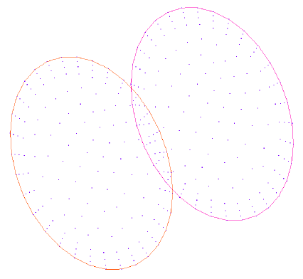
Figure 1.
Example
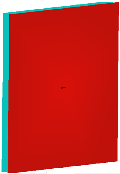
Figure 2.
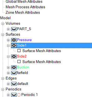
Figure 3.
The distance between the periodic surfaces must be known. If it not known, it can be found by selecting the surface in the Model Tree and right-clicking on the surface name. When this is done a menu will appear. Selecting Info will provide maximum x, y and z coordinates of the surface.
Repeat for both surfaces to determine the translational distance between the two. Once this is known the periodic parameter is ready to be defined.
Right-click on Periodics in the Data Tree and select New.
Once the new periodic has been created it will need to be defined. Right-click on the new periodic set and select Define.
This will open a dialog where the periodic set can be defined. The defining of Side 1 and Side 2 must agree with the translational off-set value, or rotational angle entered.
To select the surface to be used in the periodic set, select the eye ball or chose it from the drop down menu. If the eye ball is selected it will bring up a panel, shown below. From here the surface can be selected.
Here the surface named Side1 and Side2 are selected for Side 1 and Side 2 of the periodic set. Once these are identified, the type is selected by clicking on the drop down box next to Type.
After the type has been identified, the off-set is entered. In this model the surfaces are Side1 and Side2 and they are offset by 0.4572 meters. This means the surface named Side2 is 0.4572 meters in the positive z direction from the surface Side1.
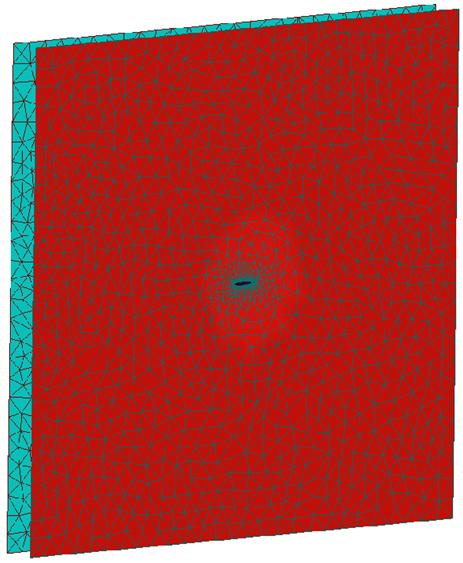
Figure 4.
The periodic matching can be examined by right-clicking on the periodic set in the Model Tree and selecting Display. A point, line or line and point can be selected to render the node matching.
Below is an example of the node matching using a line display.
Figure 5.

Figure 6.