SEA Ribbon
The ribbon allows you to quickly access tools and standard functions, and is located along the top of NVH. Click on an icon to open the related tool. Hovering over a group of icons may reveal additional tools.
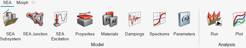
Figure 1. SEA ribbon
Tools on the ribbon are grouped logically and organized by tabs, which appear along the top of the ribbon. When you click on any of the tabs, the set of tools on the ribbon change to reflect the working context.
The following tools are part of the SEA ribbon.
SEA Subsystem
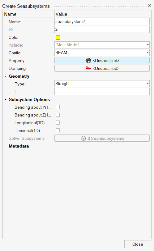
Figure 2. Create Seasubsystems
- Name
- Enter a unique name.
- ID
- Enter a unique ID.
- Config
- Element type.
- Property
- Use this field to assign a property model to the element. A property model may be chosen from the Property drop-down menu. The element materials and cross-sectional parameters defined in the selected Property record are displayed. Property records can be used to simplify the model definition in cases where many elements have the same properties. Use Property to define additional property models.
- Damping
- Specify the damping to the particular subsystem.
- Geometry
- Based on the element type, update the geometry parameters.
- Subsystem Options
- Experienced users can change the default choices for the SEA Subsystems for all element types. For certain structural element types, you can adjust the default bending stiffness or conductance of the element and add non-structural mass, component mass, or fluid loading to the element. When the options have been changed, the changes are indicated on the subsystem entity form in the SEA Subsystems field.
SEA Junction
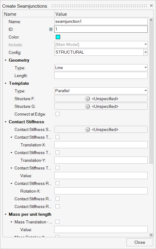
Figure 3. Create Seamjunctions
- Junction
- A SEA junction is an energy flow path between two or more SEA subsystems corresponding to a single degree of freedom.
- Connection
- Defines how model elements are connected. Connections provide paths for vibration and acoustic power flow between elements and establish degrees-of-freedom at the element interfaces. A single connection contains one or more SEA junctions.
- Name
- Enter a unique name.
- ID
- Enter a unique ID.
- Connection type
- A predefined type which describes the general form of the connection. The connection type is chosen from the Config drop-down menu.
- Geometry
- Choose the type of structural connection and specify its dimension.
- Template
- A variety of connection templates are available. Template details (highlighted) are available.
- Contact Stiffness
- Model element contact stiffness (or element contact stiffness per unit length for line junctions) due to isolation systems. Stiffness values for various degrees of freedom are entered. A blank or zero stiffness indicates no isolation is present for the DOF. Multiple elements in a connection may be isolated. Frequency-dependent stiffness may be defined using a function.
- Mass per unit length
- Translational and/or rotational masses at a junction (or mass/length for line junctions) are specified in this section. A junction mass changes the junction impedance, which may reduce or otherwise change the coupling between the elements in the connection. A translational mass changes the junction impedance for all translational degrees of freedom and a rotational mass changes the junction impedance for all rotational degrees of freedom. Frequency-dependent masses may be defined using a function.
- Constrained DOFs
- Structural junctions typically involve translation and rotation through several degrees of freedom (DOF). This option allows you to block energy transmission through any DOF by constraining its motion. Physically, constraining a DOF in SEA means that the elements are free to move (translate or rotate) without causing a reaction or transmitting energy to other elements in the connection. This is opposite of the definition of a constrained DOF in an FEA model, where the elements at the DOF are rigidly constrained to have no relative motion.
- Cross Coupling
- Cross coupling junctions connect the bending and in-plane subsystems within the same structure. This coupling is observed for real-world structures, even when the junction appears symmetric.
SEA Excitation
An excitation is generated from an input load. An excitation acts on an SEA subsystem or junction, whereas an input load acts on a Altair SEAM element or connection.
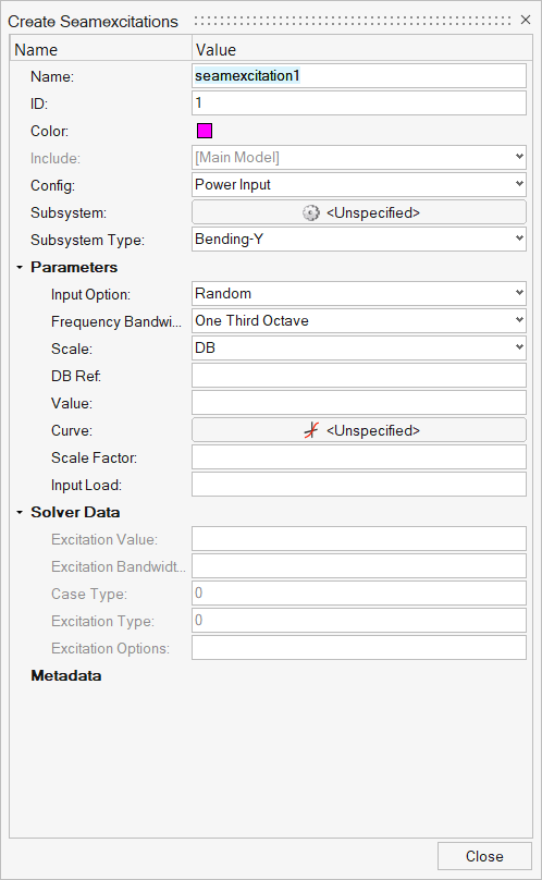
Figure 4. Create Seamexcitations
- Name
- Enter a unique name.
- ID
- Enter a unique ID.
- Input Load
- Power input to the model from vibration and acoustic sources.
- Config type
- A predefined type which describes the general form of the Input Load.
The Input Load type is chosen from the Config drop-down menu.Note: The Input Load type determines the Input Load parameters, so the Input button remains inactive until an Input Load type is selected.
- Subsystem
- Subsystem on which the load is applied.
- Subsystem Type
- Subsystem type forces on which the load is applied.
Properties
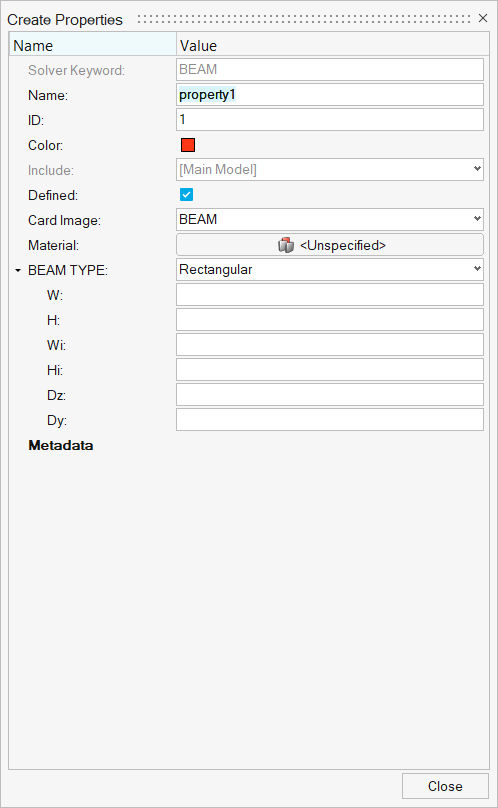
Figure 5. Create Properties
- Name
- Enter a unique name.
- ID
- Enter a unique ID.
- Card Image
- A predefined type which describes the general form of the element that
the property can be applied to. The property type is chosen from the
Card Image drop-down menu.Note: The property type determines the property parameters so the Input button remains inactive until a property type is selected.
- Material
- Assign material models to the property. The number of materials required depends on the element cross-section. For example, a layered cross-section can contain up to four materials. In these cases, you must enter a material in the first data cell. A material may be chosen from the drop-down menus located in the material field. These lists contain all predefined models which apply to the current property type.
- Type
- Options based on the Card Image type selected.
Dampings
Damping models are used to associate damping properties with an element. The damping models in SEAM can be used for many complex applications.
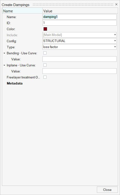
Figure 6. Create Dampings
- Name
- Enter a unique name.
- ID
- Enter a unique ID.
- Damping Type
- A predefined type which describes the general form of the damping. The
damping type is chosen from the Config drop-down menu.Note: The damping type determines the damping parameters.
- Parameters
- Use the parameter fields to enter the data for the damping model. The
parameter fields that are displayed depend on the damping type
selected:
- Structural Damping parameters
- Acoustic Damping parameters
Parameters
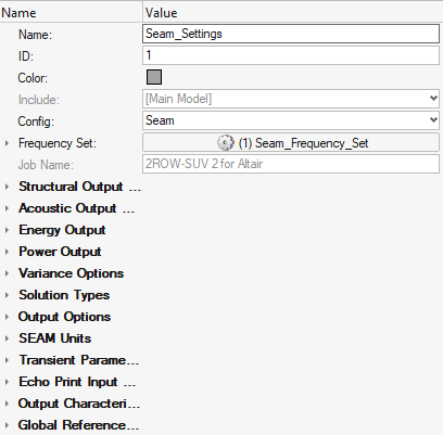
Figure 7. Create Parameters
- Structural Output
- Specifies the output reference quantity for structural subsystems. A reference value is required to normalize the output. For example, for global units of IPS, to get the structural response in g’s, select acceleration with a reference value of 386 (in/sec2).
- Acoustic Output
- Specifies the output reference quantity for acoustic subsystems. A reference value is required to normalize the output.
- Energy Output
- Specifies the output reference energy quantity for all subsystems. This value is not currently used in SEAM. Set the energy output reference quantity by editing the second entry on Line 12 of the SEAM parameter file.
- Power Output
- Specifies the output reference power quantity, including modal power, for all subsystems. This value is not currently used in SEAM. Set the power output reference quantity by editing the first entry on Line 12 of the SEAM parameter file.
- Variance Options
- Specifies the type of variance analysis, if any.
- None
- Omits the variance analysis.
- Analysis Bandwidth
- Uses the bandwidth specified in the Frequency Limits field for the variance analysis.
- Narrowband
- Performs a variance analysis.
- Solution Type
- Specifies if the analysis is steady-state or transient.
- Output Options
- Specifies if the output is in decibels or linear values.
- SEAM Unit
- Specifies the units the model is represented in.
- Transient Parameters
- Specifies options for the Transient Solution type.
- Output Options
- Specifies the format of the output quantities of responses.
- Echo Print Input
- Specifies the input files to echo in the output file.
- Output Characteristics
- Specifies the output quantities printed in the output file. If Response output is selected, you can output the response from all elements and subsystems or only selected subsystems by clicking and selecting one or more elements in the model. This is useful if the model has many elements and attention is focused on a smaller subset of elements.
- Global Reference
- Specifies the reference values required to normalize the output for different kinds of output.
Run
Run the SEAM code to analyze the model after it has been generated. SEAM displays its progress, which may be closed after the run is completed.
Plot
- Results
- Results contains the list of responses available from solving the loaded model.
-
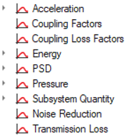
Figure 8. - Subsystems
- After selecting the result type, select a subsystem.
- Plot Section
- Used to display results of the analysis in a 2D plot.
-
- Energy Flow
- Present the energy flow after running a model for a particular subsystem. The energy flow into a given subsystem is plotted versus the connected subsystem and is displayed in the SEAM Energy Flow Graph window. A positive value represents energy flow into the subsystem, and a negative value represents energy flow out of the subsystem.
-
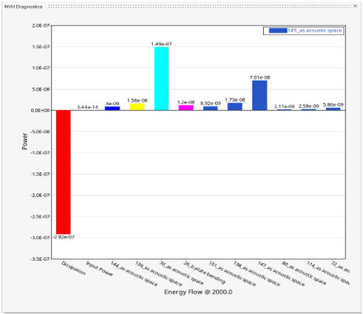
Figure 9. Energy Flow - Table View
- Provides a spreadsheet view of SEAM results. This view displays the actual numerical values of the calculated quantities.
-
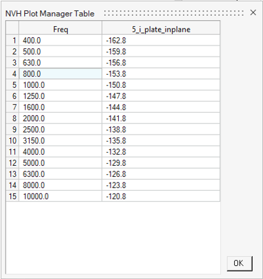
Figure 10. Table view