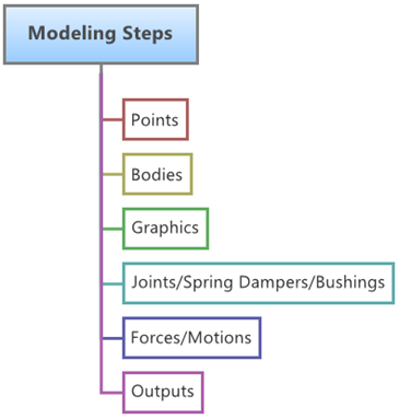
The Points tool allows you to add points to models and edit point
coordinates.
Points are one of the fundamental construction
elements for multibody models built in MotionView. Also, almost
all the entities that can be created in MotionView need to use
points either for defining their location or orientation. Therefore the creation of points is
an important task in model building within MotionView Figure 1.
In MotionView you can create the following types of
points:
Single Point
Point Pair (Asymmetric or Symmetric)
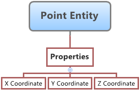
Point Entity Properties
A Point entity is defined by its three Cartesian coordinates X, Y and Z. Figure 2. Point Entity – Properties Map
A Point entity (like most of the entities that are created in MotionView) can be a Single entity or a Pair entity. The Pair entities
help in creating models which are symmetric about the Z-X Plane of the model. Their
properties can also be symmetric about the Z-X Plane (in other words, the Y property is
mirrored). Asymmetry or Symmetry of the points can be decided or specified when editing the
created point.
The Points panel contains the following tabs:
Properties
Measure
Create Points
Add a point to the model with the Points tool.
From the Project Browser, select the system to which the point is to be
added.
Right-click on a system folder in the Project Browser and select Add >
Reference Entity > Point from the context menu.
OR
Right-click on a point folder in the Project Browser and select Add Point from
the context menu.
OR
Right-click the Points panel button on the Reference toolbar.
The Add Point or PointPair dialog
opens.
Click the System collector to identify the system or
container into which the point will be created.
The Model label means that the point will be created in the main model.
By
default, points are created in a model level Cartesian coordinate system
called the Global Reference Frame. This is the only coordinate system
currently available.
Specify a label for the point.
Specify a variable name for the point.
By default, variable names of entities in MotionView follow a certain convention. For example, all point entities have a variable
name starting with “p_”. This is the recommended convention to follow when
building models in MotionView since it has many advantages in model editing and
model manipulation.
Select whether to create a single point or a point pair.
A point entity, like most of the entities that are created in MotionView, can be a single entity or a pair entity. Pair
entities help to create models that are symmetric about the Z-X plane of the
model. Their properties can also be symmetric about the Z-X plane (in other
words, the Y property is mirrored). Asymmetry or symmetry of the points can be
decided or specified when editing the created point.
Click OK to close the window or
Apply to continue creating entities.
Tip: Create a new point from the Project Browser by
right-clicking on the Model label (or any system/analysis of
your choice) and selecting Add > Reference Entity > Point or by right-clicking Points and selecting
New Point.
Edit Points
Change the coordinates of a point.
If the Points panel is not currently displayed, select the desired point by
clicking on it in the Project Browser or in the modeling window.
The Points panel is automatically displayed.
Edit the point's coordinates.
Note: If the selected point is a pair entity, first distinguish between the
Left and Right tabs in the
panel, and then edit the properties.
Tip: The Symmetric properties check box on the Properties tab allows
you to turn symmetry on or off. When symmetry is turned off, both sides can
be edited separately. When you turn on symmetry, you are prompted to select
a master side.
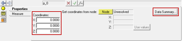
Click in the fields for the X, Y, and Z coordinates and enter a value
for each coordinate. Figure 3.
Click on Node, left-click on any graphic node in
the graphics area to extract the node's coordinates, and select
Use Values.
Note: The point’s coordinates are
extracted from the node of a file graphic defined using an H3D file that
exists in the model and is visible in the modeling window.
Click on Data Summary, select the text box of the
desired point, and edit the values.
Measure the Distance Between Two Points
Find the distance between points in the x, y, and z directions.
Select a point from the Project Browser.
From the Points panel, click the Measure tab.
Select a reference marker using the Marker collector.
Select a first and a second point from the modeling window.
The distance between the two points, as well as the magnitude, is
displayed.