Seat Mechanism
Create and articulate a kinematic mechanism based on FE mesh using the Mechanism Browser.
From the menu bar, click .
You can undo and redo actions made in the Mechanism Browser using the Undo and Redo commands on the Restore toolbar.
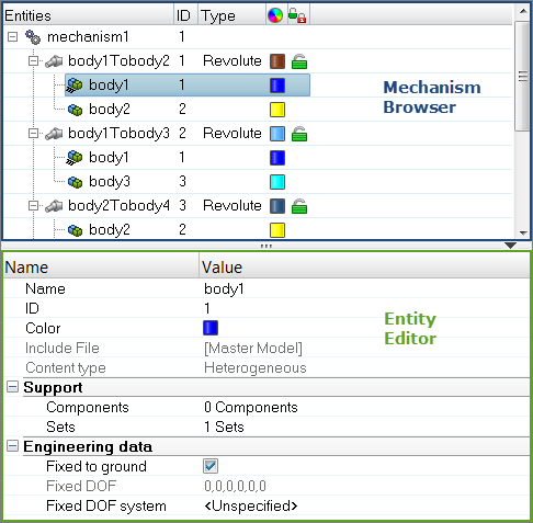
Figure 1.
| Column | Description |
|---|---|
| Entity | Lists the mechanism, joints, bodies, and constraints in your model. |
| ID | Displays the mechanism, joints, bodies, and constraints IDs. |
| Type | Displays the joint or constraints type. |
| Color | Displays the joint and body entity colors. Body color is different from the component color set-up in the Model Browser. The body color is activated when a body is in Review mode. |
| Lock level | Displays the lock level of a joint (green = free joint, yellow = locked joint). |
Entity Editor
The Entity Editor is used to assign, modify and quickly view the attributes defined inside Mechanism Browser entities.
For example, once you create a new body or select a body in the browser, the Entity Editor opens and displays the bodies corresponding attributes, which you can view and modify.
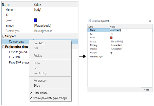
Figure 2.
Context Menu
Supported Entities
- Bodies (
 ) define
a kinematic assembly made of FE parts or nodes, which can be selected in the
Entity Editor. To create a body, right-click on
the Mechanism and select from the context menu.
) define
a kinematic assembly made of FE parts or nodes, which can be selected in the
Entity Editor. To create a body, right-click on
the Mechanism and select from the context menu. - Joints (
 ) define
the kinematic relationship between two bodies (for the following joint
types: Ball, Cylinder, Revolute, Slider) or three bodies (for the
DoubleSlider joint). To create a joint, select two bodies to connect in the
browser, then right-click and select Connect from the
context menu. For the DoubleSlider joint, the
third body has to be defined in the Entity Editor.
) define
the kinematic relationship between two bodies (for the following joint
types: Ball, Cylinder, Revolute, Slider) or three bodies (for the
DoubleSlider joint). To create a joint, select two bodies to connect in the
browser, then right-click and select Connect from the
context menu. For the DoubleSlider joint, the
third body has to be defined in the Entity Editor. - Constraints (
 ) define
kinematical constraints on a body at a specified node or point
location.
) define
kinematical constraints on a body at a specified node or point
location.
Supported Keywords Exported in Solver Deck
The mechanism information is embedded in the input deck using keywords following the /END (for Radioss), *END (for LS-DYNA), ENDDADTA (for OptiStruct/Nastran) and *END STEP (for Abaqus).
- /ASSEMBLY defines a body with the following
attributes:
- Assembly ID
- Assembly name
- Number of part sets and related set IDs
- Number of parts and related part IDs
- Number of node sets and related set IDs
- Locked degrees of freedom
- Optional local coordinate system
- /CONNECTION defines a joint between assemblies with the
following attributes:
- Connection name
- Assembly ID #1
- Assembly ID #2
- Connection position (defined by Node IDs or connection position coordinates)
- Joint limits in + and - directions
- Current joint distance/angle value
- Lock level
- Assembly ID #3 (for the Double Slider only)
- Scale factors for relative displacement between Assembly #3 and Assembly #1 and #2
- /POSITION defines, for a stored position, the position
information for the mechanism’s assemblies with the following attributes:
- Position name
- Assemblies position matrixesNote: The Reference and Initial positions should never be deleted inside the mechanism.
- /CHILD_DUMMY defines the coupling between a mechanism and
a dummy with the following attributes:
- Name
- Main assembly ID of the mechanism
- Dummy ID
- Number of child assemblies of the dummy
- Degrees of freedom linking main to child
- Child assembly IDs of the dummy
Create a Mechanism
This task explains how to create a mechanism.
There are two ways to create a mechanism: Manual and Auto Generate. In this task, you will create a mechanism using the Auto Generate method.
- Using the Manual approach, you create the mechanism manually by defining the bodies and joints.
- Using the Auto Generate approach, HyperMesh will automatically create bodies and joints based on a selection of components and elements of the FE model.
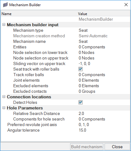
Figure 3.
Mechanism Builder Options Table
Use this table to set options for the Mechanism Builder.
| Mechanism Builder Options | |
|---|---|
| Option | Action |
| Mechanism Type | Select the type of mechanism, either Seat or General. Your selection will affect other options in the dialog. |
| Mechanism Name | Type the name you want to give to the mechanism after the extraction is completed. |
| Entities | Select the FE components that define the mechanism. You can choose Components, Mechanisms, Assemblies or Sets. |
| Node Selection on Lower Track | When the Mechanism Type is set to Seat, you can select nodes on the lower track components of the seat. |
| Node Selection on Upper Track | When the Mechanism Type is set to Seat, you can select nodes on the upper track components of the seat. |
| Sliding Vector on Upper Track | When the Mechanism Type is set to Seat, you can specify the translation direction of the joint defined for the seat track. |
| Seat Track with Roller Balls | When the Mechanism Type is set to Seat, you can specify whether the seat track contains roller balls. If you check this option, HyperMesh will automatically create a double slider joint for the seat track, and an additional selector for the seat track roller will appear. |
| Track Roller Balls | When the Mechanism Type is set to Seat, and Seat Track with Roller Balls is checked, this option allows you to select the roller ball components that will be defined as third body in the double slider joint. |
| Joint Elements | Select the FE elements (springs or beams) that have to be created as joints in the mechanism extraction process. |
| Excluded Elements | Select the FE elements that should be excluded from the extraction
process of the mechanism. For example, nodal rigid bodies that are used to link components in the FE model but that are not physical conditions, can be selected here and will not be considered in the extraction process. |
| Excluded Contacts | Select to exclude tied contacts that may be defined on the FE model but do not represent physical connections. This excludes them from the extraction logic. |
| Detect Holes | Select to activate the hole detection parameters. This allows you to detect joint positions by looking for concentric holes in components. |
| Relative Search Distance | When Detect Holes is checked, this option defines the distance of search for concentric holes that define a joint location. |
| Components for Hole Search | When Detect Holes is checked, this option allows you to select the components on which the hole detection must be performed. |
| Preferred Revolute Joint Axis | Type the vector that defines the revolute joint axis. This will overwrite the direction of the joint elements. |
| Angular Tolerance | Type the angular tolerance into this field. The joint axis within this angle will be overwritten by the Preferred Revolute Joint Axis value. |
Position Mechanisms and Joints
Overview of how to modify the position of mechanism and joints.
Modify the Position of Mechanisms
-
In the Mechanism Browser, right-click on a mechanism and
select Actuate Mechanism from the context menu, then choose from one of the following:
- Choose Translate to open the Entity Editor and select a Node/Constraint, give a
Direction of motion, and define the Magnitude of the translation to
apply.The Magnitude can also be modified, using the up and down arrow buttons. Moreover, you can control the increments of the operations by changing the Increment value.
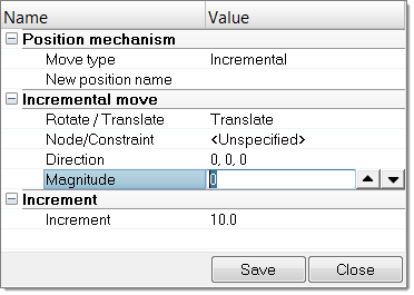
Figure 4. - Choose Rotate to open the Entity Editor, select a Body, define a Rotation axis, a
rotation center (Base point), and provide the Magnitude of the rotation to
apply to the body.The Magnitude can also be modified, using the up and down arrow buttons. Moreover, you can control the increments of the operations by changing the Increment value.
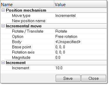
Figure 5. - Choose Target Point to open the Entity Editor, select a Node and define its Target
location. Click Move to calculate the position of
each body to bring the selected node to the target location or the nearest
location, depending on joints limit values.This option can be applied on a set of nodes and targets, by setting Multiple pairs to Yes.
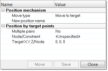
Figure 6.
- Choose Translate to open the Entity Editor and select a Node/Constraint, give a
Direction of motion, and define the Magnitude of the translation to
apply.
Modify the Position of Joints
- In the Mechanism Browser, right-click on a joint and select Move from the context menu.
-
Modify the position of the joint.
- In the graphics area, click-and-drag the manipulator.
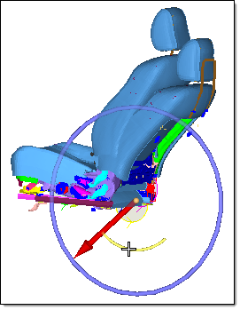
Figure 7. - In the Entity Editor, modify the Current angle
of the joint.
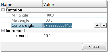
Figure 8.
- In the graphics area, click-and-drag the manipulator.
- Change the Increment value to control the increments of the operation.
Joint Coupling
Joint coupling provides functionality that allows you to create a gear joint (coupling between two revolute joints), or a rack and pinion joint (coupling between a slider joint and a revolute joint).

Figure 9.
-
To create a joint coupler, right-click on the mechanism and select from the context menu.
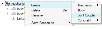
Figure 10. -
In the Entity Editor under Joints, select the two
joints to link.
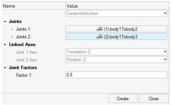
Figure 11.
Joint with Morphing
When creating slider joints, you can select additional components that will be automatically morphed along with the motion of the selected bodies.
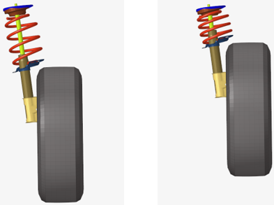
Figure 12.
-
Under Support, select the components you want to morph in the Component to
Morph field.
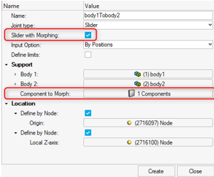
Figure 13.
Link a Dummy to a Mechanism
In a vehicle FE model, quickly and efficiently set kinematic systems such as seats, steering wheels and pedals in different positions using the Mechanism Browser.
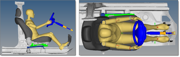
Figure 14. Initial State
Figure 15. After Translation of 100mm of the Seat