Use the Local Display Controls to change visual appearance of individual entities,
such as shaded or wireframe.
These controls are located within the tree list, and each affects the specific entity
that it appears beside.
Entity Display Icons
You can display or hide entities by toggling the corresponding icon that is located
on the left-hand side of the entities name. The following rules apply:
A bold icon next to an entity (components, multibodies, load collector, and
so on) represents that the entity is currently displayed; a dimmed icon next
to an unchecked entity represents that the entity is turned off from
display.
Assemblies containing components or multibodies are considered displayed
only when all of the contents are displayed.
Activating an assembly’s display control icon displays all of its
contents.
Activating an assembly’s display control icon displays all its components
and multibodies.
Deactivating the display control icon check box for an assembly hides all of
its components and multibodies.
Deactivating the display control icon for an item hides all of its parent
assemblies.
Deactivating the display control icon for an item does not affect the state
of its parent assembly.
An empty assembly never displays.
Colors
Assemblies, beam section collectors, blocks, components, contact surfaces, curves,
groups, load collectors, materials, properties, shapes, system collectors, tags,
titles, and vector collectors can all be colored individually. In the Model Browser, the column
displays each entity’s assigned color. To change an entity’s color, click its color
icon and select a new color from the palette. The change multiple entity colors at
once, select all of the appropriate entities, click one of the selected color icons,
and click the Autocolor button. Figure 1.
Display Mode
Components have several display states, based on a combination of their elements and
their geometry. In the Model Browser, the column
displays the display mode assigned to each component, assembly, or load collector.
To change the display state, click the entities display mode icon and then select a
new style. Depending on which option you select, the entity displays differently:
 column
displays each entity’s assigned color. To change an entity’s color, click its color
icon and select a new color from the palette. The change multiple entity colors at
once, select all of the appropriate entities, click one of the selected color icons,
and click the Autocolor button.
column
displays each entity’s assigned color. To change an entity’s color, click its color
icon and select a new color from the palette. The change multiple entity colors at
once, select all of the appropriate entities, click one of the selected color icons,
and click the Autocolor button.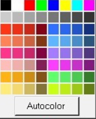
 column
displays the display mode assigned to each component, assembly, or load collector.
To change the display state, click the entities display mode icon and then select a
new style. Depending on which option you select, the entity displays differently:
column
displays the display mode assigned to each component, assembly, or load collector.
To change the display state, click the entities display mode icon and then select a
new style. Depending on which option you select, the entity displays differently:


