Model Check for CAERO1 flow direction is matching LCS in AEROS or global
Xe.
Context support for aero loading.
Context support to calculate bias table for panel meshing.
Enhance Panel mesh GUI with domain editing.
Provide facility to create/edit TABDMP1 in aeroelasticity browser.
SDAMP should be added in Solution control for Flutter.
Update ANALYSIS types as per changes in OS solver.
Resolved Issues
Error message in status bar upon creating Aero and Aeros cards from solver
browser.
Issues with accessing References from Aeroelasticity browser in a clean
settings.
Delete Advanced option not working on many entities in Aeroelasticity
browser.
Definition of PARAM card with VREF comes in model browser under
Ungrouped.
NF entry of FLFACT is converted to Real during export.
Rename FLUTTER to FMETHOD is flutter case control and export.
Remove unsupported options from Flutter methods Defect.
Unable to export model with MONPNT1 with set assigned.
"Sensor definition" details needs to remove for
MONPNT1,MONPNT2,MONPNT3.
Aero global output cards are not importing back after export.
Aero global output cards are missing from TOC solver browser.
CAERO1:Panel mesh failed with no spatial numbering.
For StaticAeroelasticResponse, ANALYSIS=SAERO.
Define Aeropanel in local system shows coordinates in global system.
Session crashes on creation of a panel mesh using LCS.
Analysis type for Static Aeroelastic Response and Aerodynamic flutter should
be set to SAERO & FLUTTER automatically.
API
See the 2021.2 API Programmer’s Guide for the full list of new features and
enhancements.
Enhancements
New Internal ID Management
From this version onwards, HyperMesh synchronises the internal IDs with
solver IDs whenever possible, the exception being models with duplicate
solver IDs (allowed in Nastran, LS-DYNA, OptiStruct and Radioss solver
interfaces).
This means for models without duplicate IDs no extra measures need to be
taken for mapping internal IDs to solver IDs and vice-versa for the
purpose of passing the correct entity identifiers to the Tcl API
commands. Note that hm_createmark, hm_getmark, or hm_getvalue commands
operate with internal IDs rather than solver IDs. The same applies when
querying entity IDs in Matrix Browser.
Assigning Parameters
Parameters can be now assigned on entity attributes using
*setvalue command, for example, *setvalue
mats id=1 Rho={parameter parameter_name}. Similarly, the
parameter can be unassigned by providing an empty name string, for
example *setvalue mats id=1 Rho={parameter "" }. Upon
unassigning the parameter, the entity attribute will automatically adopt
the same value as the one assigned via the parameter.
Browsers
New Features
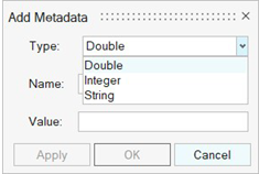
Add metadata to entities
The Add Metadata dialog facilitates adding metadata
to all the types of entities. The added metadata is saved to
*.hm file. Figure 1.
The Add Metadata dialog can be accessed by
right-clicking on an entity/folder in a browser or by right-clicking on
the Metadata category in the Entity Editor.
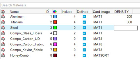
Adding metadata as a browser column is supported for entity views for
bulk reviewing or editing. An existing metadata can also be applied to
other entities of the same type from the browser column. Figure 2.
Demo Browser
New browser available in HyperMesh view menu. It allows you to quickly
open files in the Demos/hm/ folder in the
installation by double-clicking or right-clicking and selecting
open.
Entity Defaults
Entity attribute default settings is a new mechanism that allows control
of entities and the Entity Editor. It can be configured in the following
ways:
Entity attributes can be flagged as mandatory. If set, it is
shown in the Entity Editor by the red triangle in the field. As
an example, thickness could be mandatory.
Default attribute values can be defined. Once defined, creating
an entity will have those values applied. For example, the
default value for thickness may be set to 5.0.
Entity attribute fields can be removed from display. For
example, NSM can be removed from the Entity Editor display,
preventing access
The settings are stored in an EntityDefaults.xml
file and can be applied at the individual user, team, or enterprise
level.
Enhancements
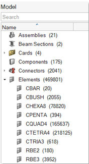
Element subcategories in Model Browser
Subcategories for elements, based on solver keyword, are now shown in
the Model Browser for OptiStruct, Nastran, and Abaqus interfaces. Figure 3.
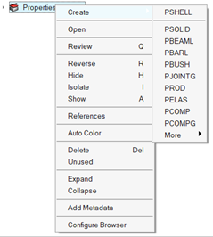
Solver keyword list for Create context menu
In OptiStrcut and Nastran interfaces, the solver keyword list under the
Create menu is redesigned to show the most used keywords at the top and
the rest under the More category. Figure 4.
Attribute columns for Systems and Vectors
Flat entity views are now supported for Systems and Vectors that
facilitate adding any entity attribute in the browser column for bulk
review and editing.
Create Part and Subsystems from Model Browser
Part and Subsystem entities can now be created from the Model
browser.
Embedded EE expand/collapse state
The expanded/collapsed state of embedded EE for referenced entities is
now retained across different selection of same entity type.
Parts from includes/subsystems
Double-click the Parts folder under an include or subsystem to show a
filtered Part Browser with just the selected parts.
Expand/collapsed state on filtering
The expanded/collapsed state of a parent entity in the browser is now
retained when a parent entity is a match for the filtering
operation.
Referenced entity check on Organize
The new Organize option with referenced entity check is now supported in
OptiStruct, Nastran, and Abaqus interfaces.
Show/Hide/Delete attached options added to Preferences
The Show/Hide/Delete attached options can now be changed from the
Preferences dialog.
Beam Section creation from Beam Section Collectors view
Beam Sections can now be created in the select Beam Section collector
from Beam Section Collectors view.
Include file creation from Include view
Under Includes view, Include File is set as the first option under
Create menu for quick creation.
Resolved Issues
Elements and nodes selected in graphics are now highlighted in browser.
Nodes are now shown in correct include when components are moved across
includes.
Geometry and FE icons for Components are now shown in Model Browser.
Local browser configuration options are now saved across sessions.
Active browser now switches upon switching browser by clicking on browser
tab.
Add Column option is now available for Component’s Property and Material
under Radioss interface.
Export CSV from the browser with special character in the name now
works.
Component no longer moves out of assembly upon tetra meshing.
Known Issues
Entity editor is not cleared when an entity is removed from the filtered
browser list.
Collected entities are not updated correctly upon making the respective
collectors inactive.
In the Demo Browser, you can only open files. Import is not supported.
In the Demo Browser, only .hm files are supported.
Certification
Enhancements
When assigning a Structural property per designpoint, a deep copy of
entities referenced by the selected Structural property is performed.
Material metadata for First_ply_Failure method are now created on all
materials with card image MAT1/MAT8 when method is created. Previously, it
was only created when method was assigned to designpointset.
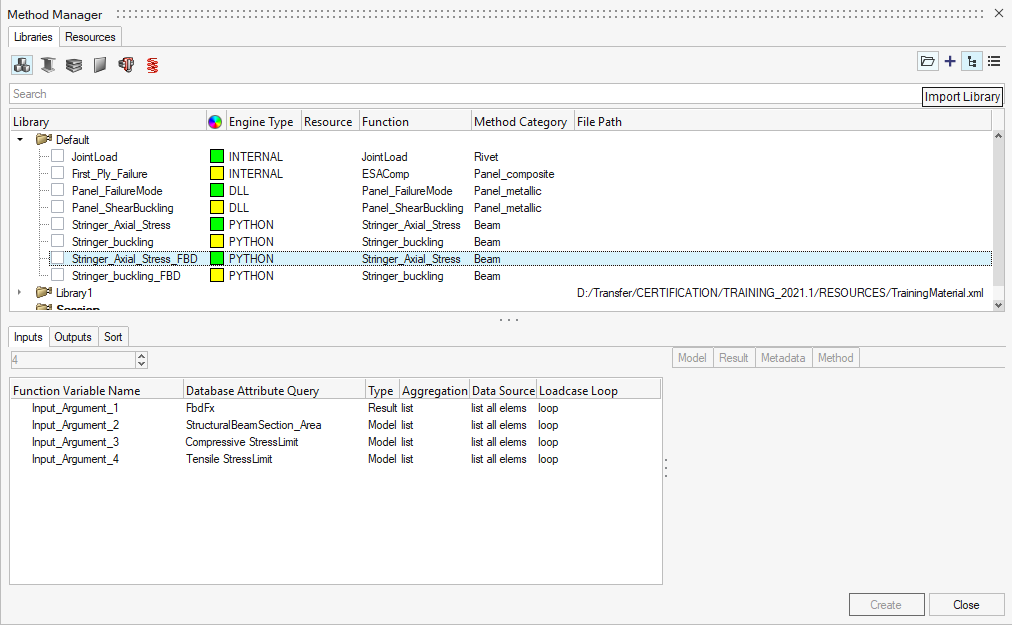
Session methods saved as a user library are auto-mounted as library and
removed from session library (hence no more duplication).
New icons in Method Manager to directly Add or Import method library.
Figure 5.
Resolved Issues
Undo/Redo of Designpoint Add/Remove is now working.
Method output argument renaming is now maintained after registration.
Method created from Registered Compose functions are now assigned the proper
engine type.
Compose registered functions are now listed as Resources on Linux.
Running multiple Designpointsets is now allowed if no method was added in
Run Context.
Running multiple Designpointsets now creates a table for the first
Designpointset in the list.
Chaining method in Linux now retrieves argument from previous method
table.
Composites
New Features
Ply Types
Ply product type support has been added for Unidirectional, Weave
(homogenized and unidirectional models), Core, and Filament Wound.
Based on the type selection, product specific details are managed by a
drape table. For example, a single wound ply type can hold a spatially
varying number tows, where each tow's thickness and orientation can
vary.
Visualization and laminate realization are supported for all ply
types.
Composite Stress Toolbox
Analysis entity stores entities (materials, plies, laminate, or zones)
along with all other analysis specific settings. This allows easy setup
of and access to classic laminate theory calculations including
engineering constants, strength, load response, and first ply
failure.
Composite plate loads (Forces and moments, strains and curvatures, and
homogenized stresses) can be created and assigned to load response/first
ply failure analyses.
Enhancements
General
Kinematic draping support added for Abaqus, Ansys, LS-DYNA, and Radioss
profiles.
MCSID visualization support in Nastran profile (accessed in Orientation
Review tool).
Composite Stress Toolbox
First ply failure methods can be created in composite browser and
assigned to laminate strength and load response/first ply failure
analyses.
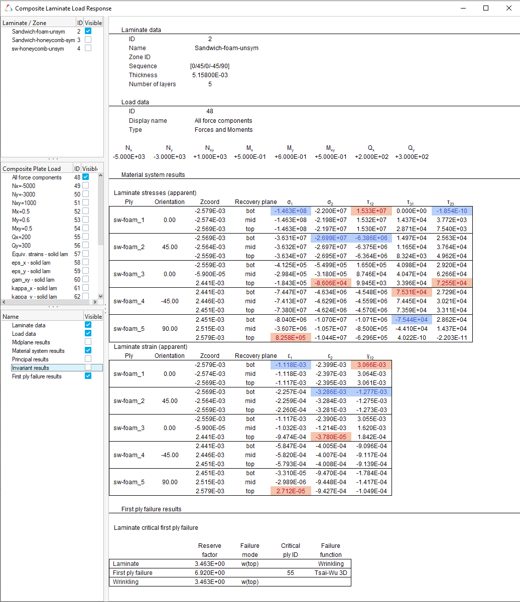
Laminate load response and first ply failure analysis provide insight to
laminate load state, material system stresses and strains, invariant and
principal results, as well as ply level first ply failure results. Figure 6.
Known Issues
Wrinkling failure in First Ply Failure method is not net supported for
Abaqus.
Drape estimator has orientation mapping issues for certain models. Kinematic
draping should be used instead.
Resolved Issues
Composite browser context menu no longer gets stuck on certain delete
operations.
Fibersim export - the correct total list of elements is now exported if a
ply has multiple sets assigned.
Drape estimator and Laminate Tools draping have been deprecated and placed
behind an environment variable. Kinematic draping should be used
instead.
Laminate spreadsheet export now writes solver ids instead of internal ids
for ply shapes.
Connectors
New Features
Auto Line
A new tool to auto-create line connectors on 2D geometry and mesh has
been added.
Master Connector File
The Master connector file has been renamed Main Connector File.
Solid Seam Imprint with Heat Affected Zone (HAZ)
Two new realisations have been added to model Seam welds with HAZ: Hexa
based realisation and Penta based realisation.
Absorb
The absorb workflows are now exposed through ribbon tools in the new
interface.
Enhancements
Attachment Improvements
Projection Attachments have been extended to Rigid Spider
Attachments.
Tags can be absorbed as Node Attachments.
The Attachment links can now be replaced in the Browser.
Attachments on solid holes have the option to realise to all the
nodes in the hole in the control.
Attachments on solid holes have the option to realise to the
solid face.
Attachments can now realise to a second washer layer.
Attachment interface ID can be altered when the Attachment is
unrealised. The ids selected are checked to ensure they're free
and then reserved.
In OptiStruct and Nastran, the Attachment name is pushed to the
interface node grid comment.
Absorbing a Rigid Spider places the Attachment at the center
node location.
Absorbing a Rigid Spider with a GRID Comment will push the name
to the Attachment.
Absorb Improvements
Absorb mechanism has more link types: Parts and Properties.
Absorb can now absorb spots as a connector spot line.
Unity Improvements
New option in the Line tool hamburger menu to merge close lines
when all selected simultaneously. It will merge all of the lines
that have a start/end at the same location.
For Point and Fastener selection for nodes and points, "Box
selection" has been set as the default. The option to turn
snapping on is in the hamburger menu under Snaps. You can then
alternate between "Box selection" and "Snapping".
Split to Points and Add Node Location as Link were added to the
Spot tool in the hamburger menu.
Auto Pitch/Auto Point new tool to map the auto pitch tools to
the new interface.
General Improvements
Connectors will no longer realise to a Realize component when
No/Skip Post has been set to on. Components are created
following a standard naming convention to ensure
consistency.
Connectors will put the Property and Material (where the
material is defined on the component) in the Component
realisation name when using No/Skip Post.
hm_createmark can now be used to select Connectors by
Subsystem.
HiLock Fastener has been adjusted to allow for PCOMPG or PCOMPP
as properties on the component links.
HM Metadata is written out in the Connector XML when
exporting.
The control binary file can now be auto-loaded by defining the
control file in the Connectors area of the Preferences
dialog.
Resolved Issues
Subsystem connectors no longer incorrectly absorb to the wrong include.
A Subsystem connector can now be reclassified as a General connector. This
will only happen if every link is present in the model, can be resolved, and
are in the same Subsystem.
Adding the control as a column no longer shows the connector control name
rather than ID.
When absorbing duplicate rigids at the same location, a single Attachment is
created.
The default for the Connector Subsystem creation is now set to Single rather
than Paired.
Connector Line tool documentation adjusted for clarity.
Using attachments with incompatible control types now shows a meaningful
error message.
Connector Combine issues resolved.
Links with ZOFFS: Bottom are processed correctly.
When the indirect option is selected, a Property in No/Skip Post is
assigned.
Part rep saving with attachments has been fixed.
HiLock now resets the mesh imprint methods when changing controls.
Importing a control binary file over an existing session updates the
connectors and no longer leaves them marked realized.
Design Explorer
New Features
Measure Response
The measure response allows you to create responses from various useful
measurements of interest: distance between, position, relative
displacement, relative angle, and angle between. In each case, you will
select the appropriate number of nodes to capture the measurement, and
the measurement will be evaluated and reported in each run of the
exploration.
Design Space
New Features
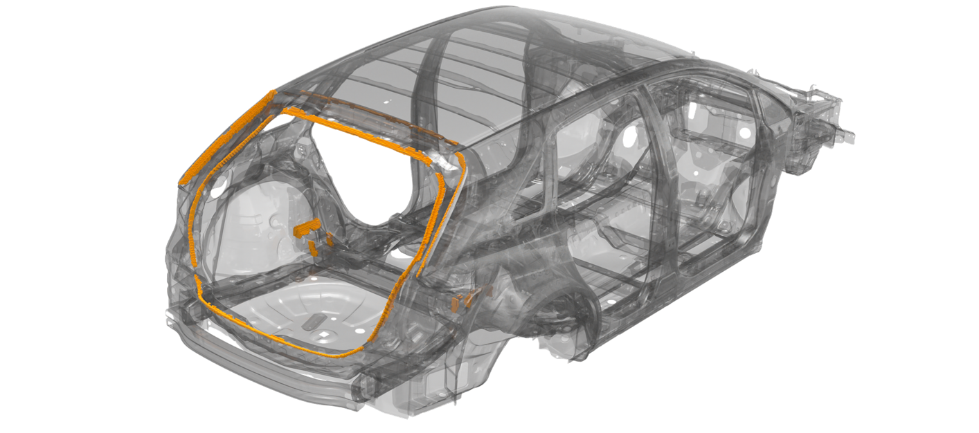
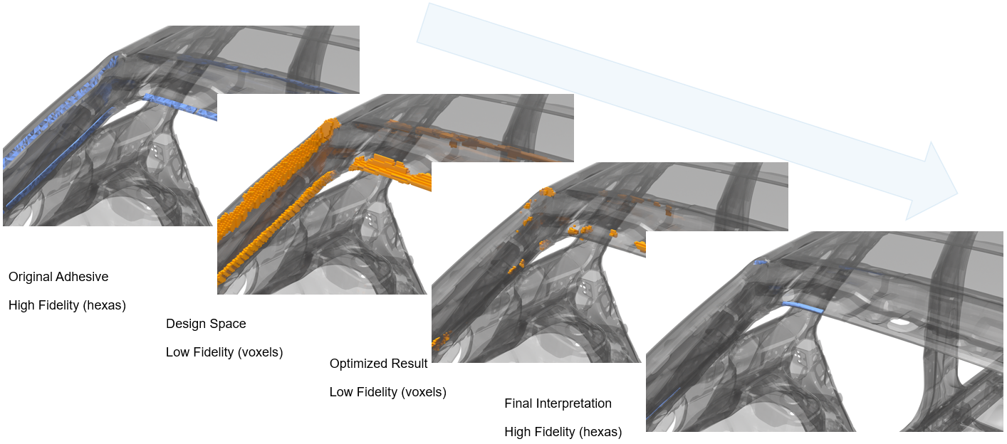
Adhesives design space workflow has been added. Adhesive tool automatically
identifies flange locations from the selected entities. It also creates a
Tie based contact between Adhesives design space (voxels) and the structural
elements nearby. It does not add any additional stiffness as it does not
create any contact between structural parts. Figure 7 used to
improve stiffness, but the adhesive length is not optimized. Figure 7. Sample Automotive Model with Structural Adhesives Figure 8. Evolution of Structural Adhesives Before and After
Optimization
Tie connect workflow has been added that generates contacts only between the
selected design space and nearby structural elements.
Fields
New Features
Supports CSV/TXT Heat Coefficent/Temperature mapping for ADVC solver profile.
Enhancements
Supports direct results mapping for:
OptiStruct
op2
Nastran
op2
xdb
ANSYS
rst
rth
Abaqus
odb
General
New Features
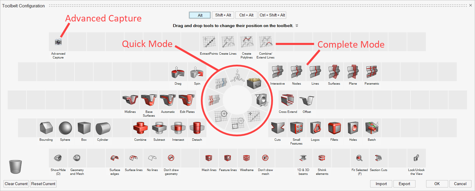
Toolbelt
The Toolbelt, a feature known from Altair Inspire, has been introduced
to HyperWorks. You can quickly access frequently used tools by using the
preset defaults or by defining a personalized Toolbelt by dragging and
dropping. Modified definitions can be exported to an
.xml file and shared with others.
To launch the Toolbelt, hold the modifier keys (ALT, ALT + CTRL, ALT +
SHIFT, ALT + CTRL + SHIFT), right-click, and drag. To define your own
Toolbelt, use the configuration menu shown in Quick or Complete Mode in
the lower left corner of the circle of tools.
Figure 9. Toolbelt in Configuration Mode
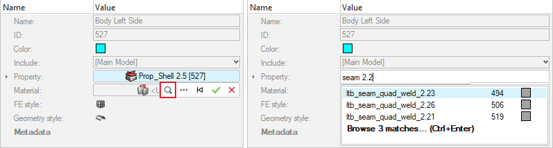
Selection search interface for Entity Editor
A new typing interface with live search suggestions is now available to
select individual entities in the Entity Editor. To select by entering
names or IDs, use the button, or press . or Ctrl > Spacebar. While typing, the selection search function provides
live suggestions of names and IDs that contain the typed search terms.
If the model contains more partial matches than listed in the
suggestions list (configurable in Preferences), you can also click
Browse More, or press Ctrl > Enter, to browse and select from the full partial match
list. Figure 10.
Figure 11.
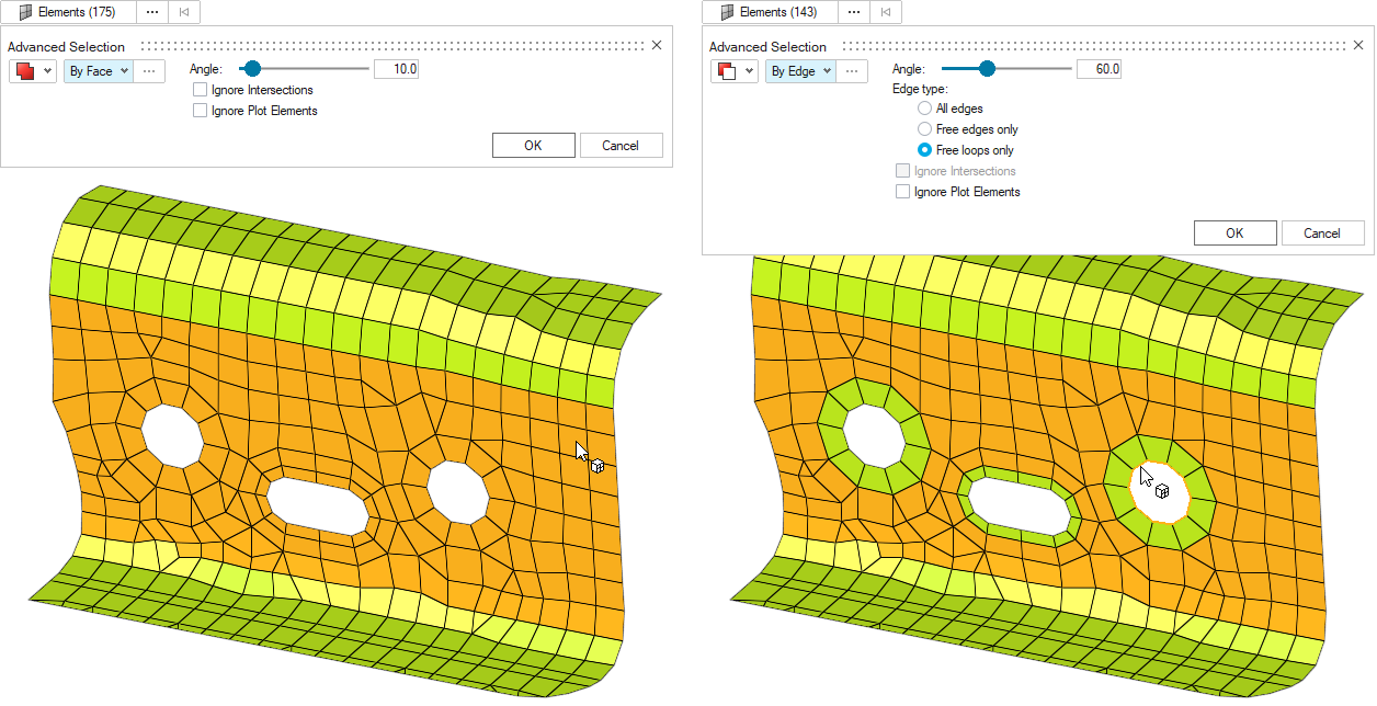
It is now possible to choose whether extended selections in the
Advanced Selection dialog will be added to,
removed from, or intersected with any current selection. The operations
can be immediately chained without leaving the dialog, so it is possible
to perform more complex actions. For example, adding elements on a face
and then removing elements from hole edges: Figure 12.
Cascaded advanced selections
The button is now also available for selection
methods inside the Advanced Selection dialog,
allowing to perform multi-level extended selections. For example,
selecting Elements, By Property, and By Include: Figure 13.
Renumber tool
A new Renumbering tool is now available on the Assembly ribbon. In
addition to a modern UI and workflow, the new tool provides enhanced
feedback and also offers the ability to renumber ordered lists of nodes
and elements.
Spatial ID Manager
A new Spatial Renumbering tool is now available on the Assembly ribbon.
It allows you to renumber nodes/elements using the system axis:
Pure spatial sorting with constant increment of ID.
Following rectangular grid schema with different increment per
direction (same as the legacy tool).
Using adjacent elements: You no longer need to select the direct
adjacent element to define direction (internal path search is
performed).
Enhancements
Selection
Set Segment contents selector in Entity Editor has been migrated from
the legacy panels to a new Entity Selector that allows appending and
deselecting the segments’ base elements directly.
Use standard selection controls to append or deselect Elements,
Facets, Faces, or Edges where the Segments are defined.
Click to reverse or align Segment
directions using the Adjust Directions
dialog. The Reverse function flips all or some Segment
directions simultaneously. The Align function is only available
for Segments defined on shell elements.
When selecting 3D elements, Segments will be added to their
outside faces only, based on the current display state.
While selecting Set Segment contents, you can freely switch
between supported selection types (for example: Elements,
Facets, Faces) and the current selections will be converted
accordingly.
Consult the product documentation for additional restrictions
and considerations for this special selector.
New advanced selection methods:
Connectors > By State (Realized, Unrealized, Failer)
FE Edges > By Path
New configurable quick advanced selection (Alt > Select) support for Tag entity.
New snap types:
Element centroid
Element edges
Preferences
HyperWorks Preferences are available in the Preferences dialog where you
can edit preferences for all loaded clients in the current session in
one place.
Some HyperMesh specific pages such as Application, Graphics, and
Browsers have been moved to the HyperMesh category in the Preferences
dialog. New additions include the Capture page for image capture and the
Export page for H3D export preferences.
Figure 14.
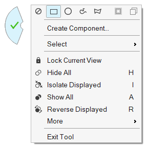
The default for swipe to exit has been changed to off. To re-enable go
to Preferences > Appearance > Context Menu > Swipe to exit. Figure 15.
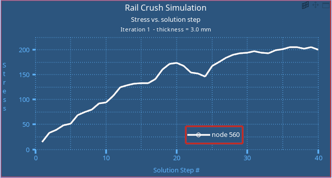
The default for plotting entity graphics has been changed to off. To
view Plot entities in the graphics window, go to Preferences > Appearance > Plots > Plot entity graphics. Figure 16.
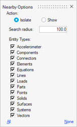
Nearby
Many more entity types are now supported for finding nearby the current
selection: Figure 17.
Model files removed from installation package
To reduce the footprint size, the following tutorial model and demo
model files are no longer included in the local installation. You can
now find zipped tutorial model files and demo model files on Altair One
via the Altair Community, Altair Marketplace, and Altair Connect sites.
Altair recommends that you create an Altair One account and use it as
your primary portal to access product documentation, a Knowledge Base,
and customer support.
Tutorial Model Files
HyperMesh
HyperWorks
HyperWorks Collaboration Tools
HyperWorks Desktop
Resolved Issues
Issues related to pinning HyperWorks to the taskbar or invoking HyperWorks
from a pin in the taskbar in Windows have been resolved. This fix applies to
all HyperWorks applications that have start menu shortcuts.
An issue affecting the display and refresh of the GUI while using a remote
display manager in next-generation applications including HW, Inspire, and
SimLab, has been fixed.
Performing quick advanced selection (Alt + Select) of Elements > By Path
with the Fill Path loops option enabled is now possible. The enclosed loop
area will be selected upon releasing the Alt key, without the need to press
MMB (since Alt + MMB is a differently assigned shortcut key).
Fixed an issue where currently selected Parts were not being automatically
inherited when entering the Move tool or other tools supporting Part
selection.
Fixed an issue where the session crashed while hovering over the undo list
in the Edit menu.
Known Issues
If you have more than one defined keyboard language, pressing ALT + SHIFT to
open the toolbelt also switches the language. The shortcuts for switching
keyboards can be modified in the Windows settings for Languages.
In HyperWorks, if you start HyperView without cleaning your settings first
and then switch to HyperMesh, the solver profile is not loaded properly,
though there is a checkmark by it in the Solver Interface menu. This results
in the loaded/available element types and full entity properties not being
visible.
Workaround: Select the solver interface from the Solver
Interface menu (File → Solver Interface), even if it already appears
selected, to manually load the profile.
Geometry
New Features
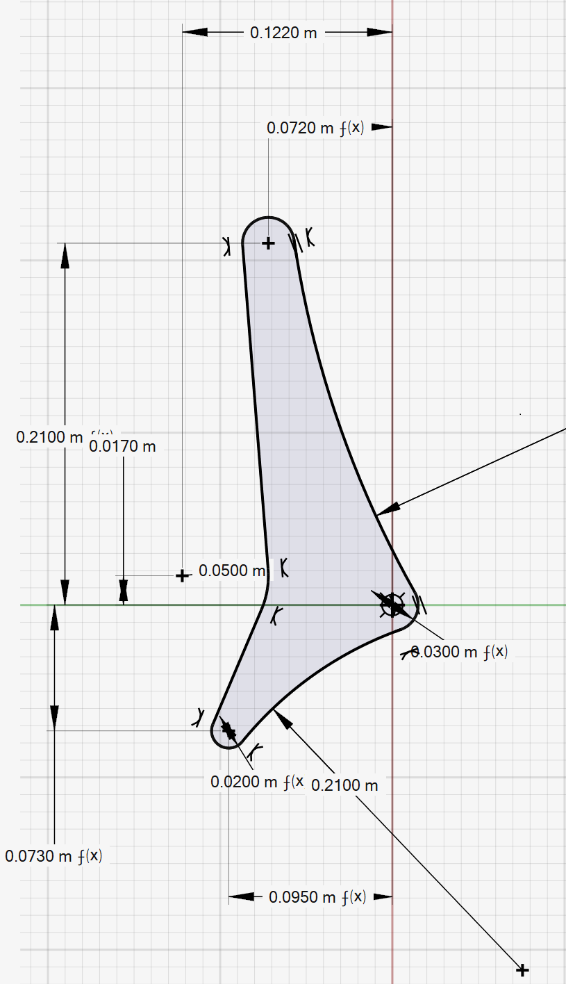
Sketch
HyperWorks 2021.2 features a new sketching interface and a number of new
sketching tools. You can create sketches, add dimensions, convert
driving dimensions to reference dimensions, and add constraints.
Highlights include:
New sketch tools: Points/Lines, Rectangles, Circles, Polygons,
Ellipses, Arcs, Splines, Dimension, Trim/Break, Extend, Fillet,
Offset, Mirror, Project, and Intersect.
Constraints: A complete set of sketching constraints are now
provided including fixed, vertical, horizontal, midpoint,
coincident, colinear, tangent, perpendicular, parallel,
concentric, and equal.
Dimensions, relations, and variables: All geometry can now be
dimensioned, and variables or relations can be used in the
dimension definition. Figure 18.
Extract tool added to the Geometry ribbon to convert sketches to
geometric lines or surfaces.
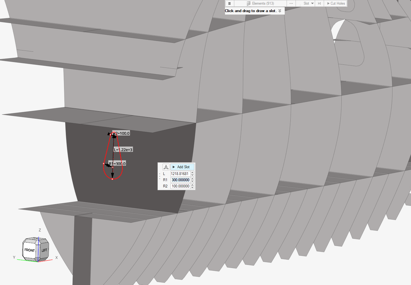
Cut Hole
New tool on the Geometry ribbon to create holes in geometry/2D mesh
using predefined shapes as:
Slots
Circles
Rectangles
Curved rectangles or curved slots
Polylines
Figure 19.
The tool includes a mesh rebuild feature to generate washers around
holes.
Enhancements
Parasolid option added to detect and remove fillets
Added auto-imprinting options for nodes and geometry creation tools
Imprint tool now supports node imprinting on lines
Splitting a line with multiple lines added
Defeature holes tool shows count of number of holes detected
Resolved Issues
Fixed issues with detection of thin solids for models with T-connected edges
for midsurface extraction
Miscellaneous issues related to ruled, split and defeature hole tools
fixed
Matrix Browser
New Features
New Access Point
The Matrix Browser can be now accessed from the Query section of the
Post ribbon. Note that Matrix is no longer accessible from the Aerospace
pull-down menu – the entire Results section has been migrated to the
Post ribbon.
Results Query
The result data coming from the Results entity in HyperMesh can now be
queried via the Matrix Browser. A new item – "results" – has been
added at the end of the list of available data names for elements and
nodes.
New Settings Options
Two new options have been added to the Settings:
Control of numeric format of the queried result values
Display of subcase and simulation name in the column header
Enhancements
Solver IDs vs Internal IDs
The Matrix Browser lists the internal IDs in the entity query column.
Historically, this has posed challenges when exporting the data and
matching it with solver data because the internal and solver ID were
often different. Thanks to the new internal ID management, HyperMesh now
synchronizes the internal IDs with solver IDs whenever possible, the
exception being models with duplicate solver IDs (allowed in Nastran,
LS-DYNA, OptiStruct, and Radioss solver interfaces). Also, the solver ID
is now available across all the entities as a core data name, and it can
be directly queried in the Matrix Browser.
Removed Deprecated Data Source
The MatDB data source has been removed from the selection list.
Known Issues
The results query is not yet supported by the macro recording. This
requirement will be addressed in the future release.
Meshing
2D Meshing
New Features
Associativity to geometry
Always maintain original node associativity to geometry like
vertices/edges/surfaces/solids. Most geometry, meshing, and mesh editing
tools, with a few exceptions, are instrumented to use new associativity.
Mesh will no longer lose geometry associativity on editing.
Edit Elements
Added Origin tool to review associated nodes moved away from the
geometry and move them back to their initial positions.
Doubler
Doubler workflow has been added under 2D → Mesh to create a part that
provides localized performance benefits for multiple design attributes
such as NVH, Safety, and so on. The workflow creates the physical part
at the desired location, applies thickness and material properties, and
also connects the part to the surrounding structure.
Edge layer mesh controls
Edge layer mesh controls added to generate 2D BL layers.
Enhancements
General 2D mesh and Panel Mesh
Added “Element organization” and “Treatment to connected mesh”
options at local context level.
Enhanced Face Edit tool workflow and added new mapping method
for Map as Triangle (Tria centre and Tria corner).
Extended support for number of layers upon Redo
connectivity.
Edit Elements
Replicate tool enhanced to Auto detect FE stitch shared edges
with 2d-3d elements.
Edit Density tool supports element re-mesh with specified number
of layers.
Box trim UI and workflow enhanced.
Section Property (in Mesh 1D Group)
Performance improvements when intersecting 3D
elements
New feature to consolidate the beamsections resulting
from multiple cuts using a tolerance on calculated
moments of inertia. This reduces a lot the number of
section created.
New option to translate beams to the actual shear center
location instead of applying offset
1D Beam Review
New flag to review offset values as tooltip while
hovering mouse on element
New item in legend to display orientation vector along
with x,y,z elemental system
Bulkhead
Within the bulkhead workflow, it is now possible to
apply the material to the newly created part.
Resolved Issues
Fixed miscellaneous issues in the Refine tool and addressed
inconsistencies.
Midmesh Align distorting mesh resolved.
Fixed topology revision issues related to remeshing of geometry after
unstitching of T-connections
Solid Meshing
New Features
Added “Thin Solid” tool in Mesh ribbon to generate Hexa-Penta mesh on thin
solids like sheet metal solids and electronic components having relatively
smaller thickness.
Resolved Issues
Resolved “Growth Rate” issue related to Tetra mesh.
Solid Map tool now allows selection of partial mapped solids upon clicking
on “Find” option.
TetraMesh panel bug (application hang) pertaining to the Abaqus profile
fixed.
Model Build
New Features
PDM Live connections
HyperMesh can interact directly with PDM
systems via the Part Browser. It can download/upload data to PDM systems
from within Part Browser on Demand. This makes the HyperMesh-PDM integration more robust and very
intuitive, helping the CAE world to work seamlessly with the PDM
world.
Enhancements
Identifying and linking symmetric parts as instances is now supported.
Support for parts and instances is added to the Mirror tool. Mirroring a
part with "Keep original" will create a new mirrored instance of the
selected parts.
When loading part representations, there is now a progress bar so you know
how far through the load process you are.
Resolves Issues
When a component is moved from one part to another, it is no longer
automatically transformed by the new part's position; it is instead left in
the same position in space.
After going to a New Model in a HyperWorks
session, the Model subsystem is no longer exposed.
The subsystem icon will now update when parts or components are shown,
hidden, or isolated so you can check which subsystems are displayed.
Since connectors are listed directly in the Subsystem Browser, the Connector
section from the Subsystem Entity Editor has been removed.
Creation of multiple subsystems from Includes now creates subsystems in the
same order as the Includes.
The Library and Export Deck options were available in the Subsystem Browser
only in HyperWorks. They are now available in
HyperMesh as well
Model Verification
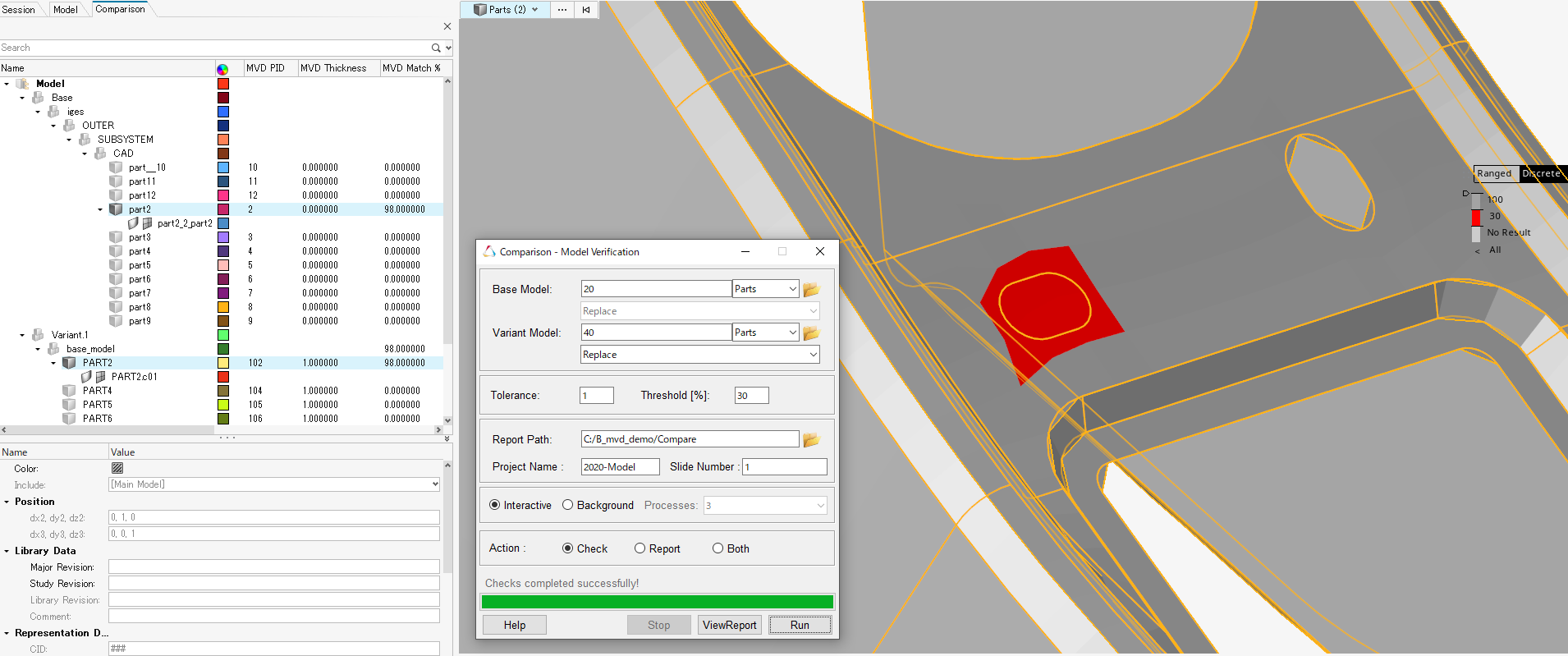
New Features
Quick Comparison works for user-selected Parts directly from HyperWorks
graphics. Figure 20.
Export unmatched surfaces to 3D data for CAD vs CAD Comparison with DLT
string appended on the exported CAD file.
User-defined metadata values can be selected and appended to the existing
Excel report through Tool/Edit Excel utility.
Auto-migration of configuration file supported for both major and minor
version as well.
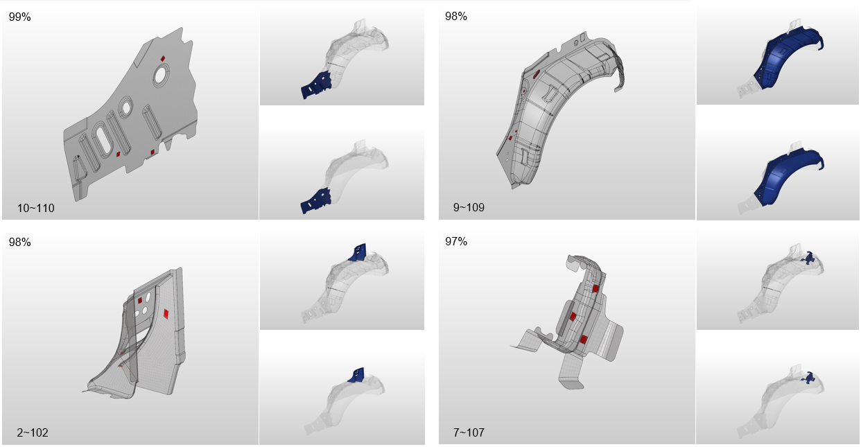
Enhancements
CAD vs FE comparison, matched area is shown in transparent mode in the
PowerPoint thumbnail images. Unmatched area is shown in shaded mode. Figure 21.
BOM Comparison displays 31% Match if Part Revision is mismatching but Parts
Name/Number/PID is matching.
Merge Comparison Excel reports to single/few based on user input. For every
result ranges, MergeExcel.xlsm is created.
Skip calculating Oriented BBox from Cad or FE if component has zero
nodes/surfaces.
New Part pair Revision filters are added (Same-Pid-Only+Revision....).
BBOX creation is improved to exclude scattered parts while calculating and
distributing parts for the parallel processing.
Connection Holes-Mismatch and Holes-Pair-Mismatch checks are parallelized
for the reports.
File size check is added before attaching the common representation to a
Part (applicable to offset function).
Part Match function the #solids count depends on Parameter.
Connection Check and Report, Parallel session starts after 10min of delay to
accommodate load balance.
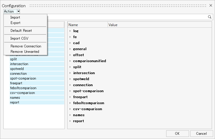
Delete Connection/Unwanted filter groups from configuration file at
once. Figure 22.
Relocation of Parameters
All color related parameters for the comparison function is moved under
compareunified/report/color.
BOM Comparison related parameters are moved compareunified/Bom
comparison
String Range parameter for controllling Part Name, Number, Assembly names
are moved under general/tool.
Resolved Issues
After an MVD run, configuration from mvd temp folder was active.
Connection Check, hm_getmark errors displayed on huge models.
Part Match, renaming Part Set name considers PartName in addition to
PartNumber.
Mixed Import, will work directly from Intersection GUI.
BOM Comparison, Part color is being displayed for unmatched range when 3
levels threshold value is chosen for CAD-CAD compare.
Representation file type gets changed from FEM to CAD file when
cadtofeapproach is executed using browser selection method for the 2nd
time.
Module Pair Ignorable filter must accept attribute PartName in addition to
PartNumber.
Configuration, Search option not working if the Tree is in a collapsed
state.
Morphing
New Features
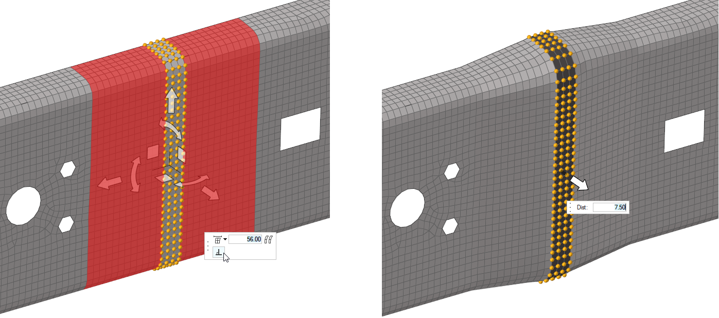
Morph Normal to Mesh
In the Free and Proximity morphing tools, it is now possible to toggle
the Move tool mode between translating & rotating (default), or
offsetting normal to mesh. Click in the Move tool
microdialog to replace the standard Move tool with a single normal
offset arrow. While in this mode, drag or click on the arrow to type a
normal offset value to move the nodes. Optionally, use the microdialog
buttons to review and edit the normals calculation options and area.
This mode is not available for nodes connected to 3D elements. Figure 23.
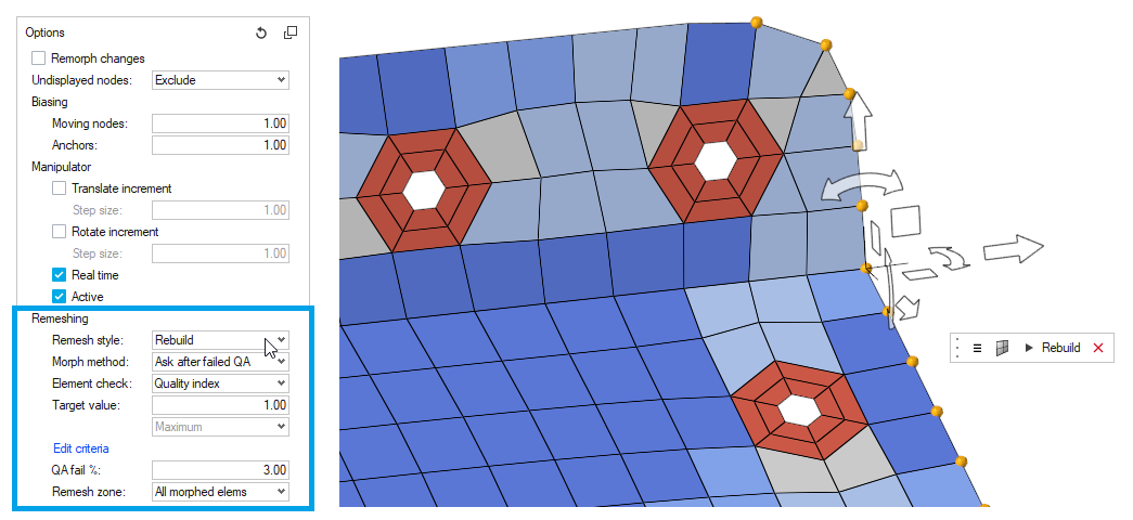
Morph Remesh and Rebuild Options
New options have been added to the Free, Proximity, and Volume morphing
tools to monitor specified element quality criteria during morphing and
automatically offer to remesh the affected elements using HyperMesh's
rebuild or remesh technologies. The morph remesh microdialog appears
when the specified remesh conditions are met, and allows reviewing and
editing of the remesh parameters and area of effect. It is also possible
to selectively skip any triggered remesh condition. When remeshing a
morphed mesh using these tools, the morphing vectors are also
automatically mapped to the new mesh, so it is still possible to save a
morph shape from the morphed and remeshed area. Figure 24.
Enhancements
Undo All Morphs
A new satellite icon has been added to the Shapes tool to provide
quicker access to the Undo All Morphs function. Use this button to
immediately undo any currently applied morphs in the current session. As
a reminder, you can also execute the Undo All Morphs and Redo All Morphs
functions while inside any morphing tool by using the keyboard shortcuts
Shift + Ctrl + Z and Shift + Ctrl +
Y, respectively.
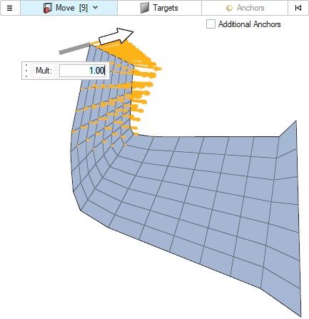
Undo Shapes as Morph Input
It is now possible to select existing morph Shapes as input to create
new morphs using the Free and Proximity morphing tools. When selecting a
Shape, the Move tool is replaced by a shape magnitude arrow that can be
used to move the nodes freely along their Shape. The magnitude is in the
form of a multiplying factor with respect to the selected shape. Figure 25.
Other enhancements
Changed the default values for the 1D/connector automatic
clustering parameters in the global section of the morph
options. The new defaults represent less constrained morphing
conditions that can speed up many morphing scenarios
significantly. Models already created and saved using the
previous default values will not be affected, as these settings
are saved with the model. The new default values for these
options are:
Connector/cluster/eq morphing = use doms/mvols
Stretch mesh around clusters = off
Morph volumes are now temporarily hidden from view while
animating morph shapes.
Resolved Issues
Fixed a performance issue in Proximity morphing where using the "Morph only
connected nodes" option could cause additional delays in some models.
Fixed an issue introduced in version 2021.1 where the automatic Morph Area
detection in the Free morphing tool was sometimes propagating beyond the
expected connected faces.
Fixed an issue where microdialogs could post in an overlapped manner in some
morphing tools.
Post
Highlights
A brand new set of tools and workflows has been released in HyperWorks (HM) on the
Post ribbon to allow direct integration of native results readers into HyperMesh and
perform results visualization on the model via:
Contour plot
Vector plot
Tensor plot
Deformation plot
The new workflows are available for the following solver profiles:
OptiStruct
Nastran
Abaqus (Plot Workflow as Beta)
ANSYS (Plot Workflow as Beta)
For all other solver profiles, the Post ribbon hosts a configuration which points to
older panels for Contour, Vector, Deformed, and Transient workflows, which rely on
*.res file availability.
Plotting
New Features
Importing Results
Results can be imported directly into HyperMesh using File > Import > Results.
Currently supported solver related extensions are:
OptiStruct (h3d, op2, hdf5, h5)
Nastran (xdb, op2, hdf5, h5)
Abaqus (odb)
Ansys (rst)
Batch Import:
Load combination file (*.csv) can be used to import files/resources and
their relevant subcase and simulation steps to generate a result
entity.
In addition, you can create definitions of Derived Load Cases (DLC) in
form of:
Linear Combination (Superposition)
Envelopes
Results Browser
After importing the results, you are brought directly to the Post ribbon
with the Results Browser open. The browser can always be re-opened by
clicking the Results tool on the Post ribbon.
Results Hierarchy
Each imported file is shown under the main result root as a
resource.
Each load case (and simulation step) is listed under the pertinent
resource it belongs to.
New files can be added using the Import/Add
Results satellite icon.
Subcase/Simulation Status Bar
The current Subcase/Simulation can be set by:
Double-clicking the subcase/simulation entity
Right-clicking on an entity and selecting Make
Current.
By changing the active collector on the status bar at the bottom
of the application.
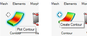
Plotting Tools
Each plot workflow relies on a plot control entity and can be accessed
either via the Plot or Create options. Figure 26.
When there's no plot control of any of configuration in the database,
the Plot option creates such an entity.
Each plot control workflow on the ribbon exposes a guide bar with the
following:
Available plot control to be selected (from that specific
configuration)
Icon to expose a floating Entity Editor (EE) to set the data to
be displayed and the relevant options
Entity selector
Plot execution (without exiting the tool)
Plot execution (exiting the tool)
Clear plot
Exit tool
Data types available for each plot control are “children” of the current
subcase/simulation selected.
Any plot control can be activated (once available) from the Results
Browser by simply clicking its icon. Only one plot control per
configuration can be activated/displayed in the graphics.
Once out of the tool, the EE is shown in relevant property area in the
Results Browser.
The context menu in the Results Browser (blank area) gives access to the
Clear Plot option, which cleans the graphics and turns off the display
of all plotted controls.
Once any plot control is on/active, each modification of the EE
properties is automatically committed and the graphics are automatically
updated. This occurs as well by changing/switching to any other
subcase/simulation step.
Contour
Contour plots visualize result data by coloring entities by
value, allowing for easy identification of maximums and
minimums throughout the model. Contour plots can be created
using any scalar data, including components or invariants of
vector or tensor results (e.g. vonMises stress, displacement
magnitude).
Averaging
The standard (simple) averaging methodology
supported is equivalent to the HyperView advanced
one. That means that tensor/vector invariants are
evaluated/extracted from the full averaged tensor
quantity after each component has been averaged
with respect to a given system (Global or User
Defined).
Currently the averaging methods is
across part boundaries.
Iso Plot
Due to current graphics limitation, the elements
removed from Iso thru the slider in the legend are
still “displayed” for the database and can be
selected either via idle mode or via API.
3D Visualization
3D visualization of shells and 1D elements is
supported when a contour is applied only when the
data types are elemental bound and with single
association. Support of nodal/corner bound values
is a work in progress.
Vector
Vector plots are useful to draw arrows such that the
direction in which the arrow points is the direction of the
vector and the length of the arrow is its magnitude.
Individual vector components, shear, and complete resultants
can be plotted for vector-based results. (eg, X, Y, Z,
Resultant).
Visualization on Deformed
See Deformation [Tensor and Vector on
Deformed]
Tensor
Tensor plots are useful to analyze the overall contribution
of quantities like Stress and Strain on the relevant
entities.
Currently, only component view is supported (Principal View
is a work in progress).
Visualization on Deformed
See Deformation [Tensor and Vector on
Deformed]
Deformation
The Deformed tool is used to specify parameters for
deformation display. This displays the original structure
and the deformed shape to see the total amount of movement
or view the deformed shape by itself.
Scaling factor currently supported is limited to uniform
one.
Selection
When a deformation plot is active, window
selection is disabled.
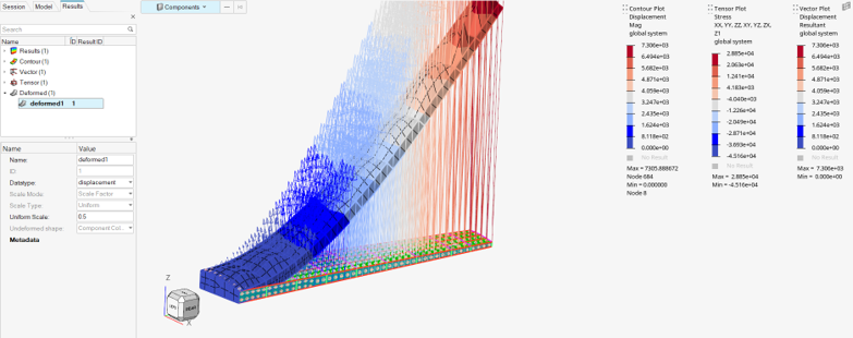
Tensor and Vector on Deformed
Vector and tensor are currently always shown in
undeformed shape. If deformation is on and either
a tensor or vector plot are displayed, an
undeformed shape (with default component color
mode) is displayed and relevant quantities are
drawn using it as reference. Figure 27.
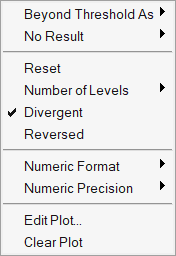
Legend
Contour, Vector, and Tensor plots display a dedicated
legend. Each result legend can be currently moved anywhere
in the graphics area, but its position is restored any time
a display operation is performed.
The legend has an associated right-click context menu. Figure 28.
Known Issues
For ANSYS (Beta), post-processing results display on 2nd order elements has
an issue when corner data are set to ON.
FBD
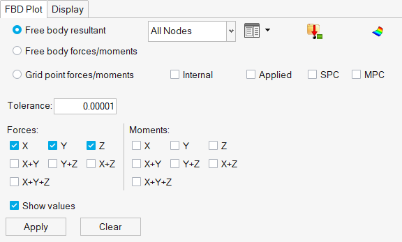
Enhancements
New layout for the display of FBD forces with better organization of data among FBD
and Grid Point Forces. Figure 29.
Resolved Issues
Correction of graphic scale factor
Resolution of results transformation with respect to cylindrical system
Resolution on Trace Plot results display depending on direction of node
path
Resolution on load creation
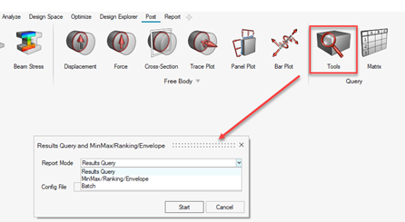
Query
Enhancements
A unique tool has been made available to invoke the setup of:
Results Query
MinMax/Ranking/Envelop
and their execution in batch mode. Figure 30.
Safety Tools
New Features
Seat Foam Deformer
This new feature allows you to perform the seat foam deformation process
directly in HyperMesh. Compared to the existing seat deformer using the
pre-simulation approach, the seat foam deformer enables you to quickly
get high quality results of the new seat foam shape, removing
intersections with the dummy.
This new feature is available in the LS-DYNA and Radioss
interfaces.
Dummy pre-simulation
A new feature in the dummy pre-simulation tool now allows you to
directly select the initial dummy file, which is then automatically used
for the simulation process. HyperWorks only exports an include file
containing the load case information and a master file referring to the
dummy and load case includes. This leads to an improvement of the
performances of the tool, reducing the time for the export of the
simulation deck.
Combined seat and dummy pre-simulation
This new feature, accessible from the Dummy pre-simulation GUI, enables
you to set a pre-simulation run to perform the seat deformation and the
dummy deformation in a single stage. This improves the occupant safety
model set-up process by reducing the simulation time requested for the
seat and dummy pre-simulation.
This new feature is available in the LS-DYNA and Radioss
interfaces.
Enhancements
Mechanism tool
The joints attributes are now fully editable after the joint creation
process, allowing an easy update of the joints. Delete and re-create the
joint is no longer requested.
Seatbelt system performances
The performances of the seatbelt system tool are drastically improved,
especially when modifications operations on the belt are applied. For
example: interactive modification, belt update on dummy & seat
motion, mesh size, or mesh type change...
Pedestrian tool
The marking of impact locations on outer surfaces is improved by
considering openings, for example on the hood.
Resolved Issues
Reading of the Radioss native H3D file to update airbag, dummy, or seat with
simulation results, is now working.
Solver Attribute Mapping
Solver Conversion
Enhancements
Abaqus to OptiStruct conversions
RIGID BODY converted to RBODY with GPAD=NONE
SHELL SECTION(SC8R) converted to PCOMPLS
CONNECTOR JOIN converted to RPIN
CONNECTOR DAMPING converted to PJOINTG, DAMP
HYPERELASTIC+*VISCOELASTIC converted to MATHE+MATVE
JOIN, ROTATION converted to RPINROTA
PLANE, ALIGN converted to INPLORIE
CONTACT CLEARENCE converted to CONTACT PAIR+MODCHG
CHANGE FRICTION converted to PCONT+TABLEG
Ansys to OptiStruct conversions
MASS21(Keyopt(3) = 2 ) converted to CONM2
MPTEMP, MPDATA,NU converted to MATT1(NU)
CONTAC173/CONTACT174/CONTACT175/CONTACT177 are converted to RBE2
when KEYOPT (2) = 2 (MPC) and slave is a 1-node PILOT NODE set
to KEYOPT(4) = 2
CONTAC173/CONTACT174/CONTACT175/CONTACT177 are converted to RBE3
when KEYOPT (2) = 2 (MPC) and slave is a 1-node PILOT NODE set
to KEYOPT(4) = 1
MPC184 converted to RBEAM Joint if KEYOPT(1) = 1 and RDOF =
blank in SECJOINT
MPC184 converted to BALL Joint if KEYOPT(1) = 16 and RDOF = 1,2
3 in SECJOINT
MPC184 converted CARTESIAN+ CARDAN Joint if KEYOPT(1) = 16 and
RDOF = blank in SECJOINT
COMBIN39p converted to PELAS/PBUSH
JOIN converted to RPIN
SECTYPE,SHELL converted to PCOMP
SECTYPE,SHELL(one layered solid) converted to PCOMPLS
SECTYPE,SHELL(SOLSH190) converted to PCOMPLS
LINK180 converted to RLINK
BEAM189 converted to CBEAM
ADVC to OptiStruct conversions
PretensionSectionElement converted to PTFORCE, PRETENS
PrestensionSectionSurfaceList converted to PTFORCE,PRETENS
InitialTemperature converted to SPC
Radioss to OptiStruct conversions
/PROP/SPR_BEAM converted to PBUSH
/ADMAS converted to CONM2
/GRAV converted to ACCEL2
Abaqus to Radioss conversions
C3D10 converted to TETRA10
C3D10I converted to TETRA10
BEAM SECTION converted to /PROP/INT_BEAM
SPRING(Nonlinear) converted to P4_SPRING
DLOAD converted to /PLOAD
DSLOAD converted to /PLOAD
INTIAL VELOCITY TYPE=ROTATION converted to /INVEL/AXIS
CONTACT INCLUSIONS,ALL ELEMENT converted to TYPE24
Dyna to Pamcrash conversions
CONTACT_AUTOMATIC_Single_Surface(with mortor) converted to
CNTAC36
CONTACT_AUTOMATIC_SURFACE_TO_SURFACE_ID(with mortor) converted
to CNTAC33
CONTACT TIED EDGE SHELL TO SURFACE converted to TIED
CAD and Solver Interfaces
Abaqus Interface
New Features
Analytical Rigids
New graphics support to visualize analytical rigid surfaces along with a
toolbox to create those surfaces.
Duplicate Names
Duplicate names are now allowed in set entity based on name pool shared
between node set, element sets, and set segments.
Contact Surface Mapping
New preference option that allows contact surface to map between shell
and solid once the base element attached to the contact surface is
deleted.
Enhancements
Auto-Surface Generation for Bolt Pretension
Pretension manager tool is enhanced with the ability to create bolt
pretension surface and node using a direction and a base node selection
option.
Rigid Body Migration
Rigid body definition is migrated from property entity to an RBODY
entity. Additional enhancements are made to reviewing the rigid
body.
New Keywords
*STEADY STATE TRANSPORT
*TRANSPORT VELOCITY
Enhanced Keywords
*DLOAD with viscous body force (VBF) label
*VISCO with default for STABILIZE
*DISTRIBUTING COUPLING with mass option removed
*ELASTIC, TYPE=SHEAR
*VISCOELASTIC, FREQUENCY=PRONY
*MAIN/SECONDARY options instead of MASTER/SLAVE on all relevant
keywords
Contact Browser
Added clearance column to the middle window of the Contact Browser.
Resolved Issues
BOUNDARY with FIXED was not exporting properly and the issue is fixed.
An issue with property and material not retaining color from HM comments is
addressed.
Improper import of DLOAD with TRVEC is fixed.
Review of surface in pretension manager was causing application error.
CONTACT STABILIZATION keyword was causing segmentation error and the issue
is addressed.
Apply quote rules for *DISTRIBUTION had issues with export.
Application error when using Abaqus parts and instances based module ID
manager is resolved.
Swapping contact pair to general contact did not convert surface interaction
property.
When Abaqus Aerospace profile is invoked, it was causing application
error.
Cleaned-up issues with quotes on names for *PSD and *CORRELATION
keywords.
Entity Editor for Tie/Contact pair was not showing all card images and the
issue is resolved.
ADVC Interface
New Features
New Cards
Support of $SubordinateNodeClearance
Support of deprecated $SlaveNodeClearance
Support of $FilmCoefficientInTable
Support of $Element HeatConvection8
Enhancements
Auto-contact function added. It can be accessed from the ribbon and the
Contact Browser context menu.
Rigid link tool is added so that you can create Rigids via a HyperWorks
workflow.
Changed Master and Slave labels to Main and Secondary for the Contacts.
Resolved Issues
Fixed an issue in Contact: adjust/gap correction parameter allows both
value/yes options
Allow reading for empty sets or segment sets in ADVC
Allow export for contactgroups even with no groups assigned
ANSYS Interface
Enhancements
Contact group header in the Contact Browser changed to Main and
Secondary.
Auto Contact updated with use shell thickness feature with options.
SHELL181p, SHELL281p real property are removed and are realized with SECTYPE
SHELL (with thickness mapped).
SOLID95p real property is removed.
Multiple data lines of super element (SE) supported.
IRLF supported at subcase level.
TBFIELD, TEMPS is supported.
CONTACT174 is updated to version18 and above.
SECTYPE, SECID, CONTACT, BOLT is supported.
EXODUS Interface
Enhancements
Rigid Spider (RBAR) and RBE3 can now be created and edited through dedicated
tools.
RBE3 is created with independent block (component) and weight factor can be
provided in all 6 DOF.
Spotweld tool is available in panels to create attachments and
connectors.
Resolved Issues
Duplicate ID warning upon import
Missing WTx input in RBE3 element
Set Segment names during import are now with ID
The Beam Section icon in the Mesh and Marine ribbons was missing
CAD Interface
Enhancements
Updated Version Support
NX 1953 (CT reader)
NX 1957 (CT reader)
Creo 7.0
Catia V5-6R2021
Solidworks 2021
Inspire 2021.2
Resolved Issues
Added an option to remove degenerated surfaces on import.
Assembly hierarchy difference issue and import failure with monolithic Step
file format fixed.
Fixed default import of hidden parts when hidden parts option turned off for
Creo assembly files.
LS-DYNA Interface
New Features
Support of LS-Dyna solver version R11.2
The LS-DYNA solver profile R11.2 is now available with the relevant
keyword updates related to this solver version.
New State Equation entity
The State Equations entity collects the LS-DYNA EOS keywords, which were
previously defined into the Property entity.
New Model Clean-Up tool
The new Clean tool on the Validate ribbon is an efficient way to delete
automatically all Empty or Unused or Undefined entities from the model,
which may be created during model modification operations.
Model units conversion
The new Unit conversion tool on the Model ribbon provides an efficient
way to convert a model from its original unit system to a new unit
system. The covered unit systems are: (N,m,s,kg); (N,mm,s,T);
(kN,mm,ms,kg); (N,mm,ms,g)
The Comment entity is enhanced to support referenced entities selection.
This provides a convenient way to defined comment lines to a dedicated
entity or group of entities. When an entity is referenced to a Comment
entity, the *COMMENT is automatically written just before the referenced
entity or group of entities.
Also, the Empty and Unused entity checks have been enhanced to consider
the Comment entity.
Intersections and Penetrations Check tool
The algorithm is improved with following enhancements:
No intersections are reported anymore when solid component faces
are exactly on the same level, or, when component shell edges
lie exactly on a solid component solid face.
Previously, for nodes which are common to multiple components
(example: T-connections, ribs on plastic parts…) the algorithm
was considering the maximum thickness of the connected
components for the calculation of the penetrations of those
common nodes. This was leading to non-valid penetrations.
A
new option “Re-check component shared nodes“ is added when
checking penetrations on a selection of components. This
option re-checks the penetrated component pairs having nodes
shared by other components in order to filter out the wrong
nodal penetrations.
Export of LS-DYNA I10 Format
A new export option is added to choose the type of i10 solver deck to
write out. The exported deck can be written with the option i10=Y in
*KEYWORD, or, with % sign at the end of each solver keywords.
Resolved Issues
ID offsets defined in multiple nested *INCLUDE_TRANSFORMs were not applied
properly for some entities.
Modification in *CONTACT_TIED_NODES_TO_SURFACE Entity Editor to avoid OFFSET
and CONSTRAINED_OFFSET options to be activated together, which was leading
to a wrong keyword definition.
*DEFINE_ELEMENT_DEATH keywords will not be found as unused when checking for
unused properties.
Correction to find correctly unused *MAT_ADD keywords when checking for
unused properties.
Unused and Empty function is added for Sensor entity.
Empty function is added on Blocks entity to identify empty *DEFINED_BOX
keywords.
Corrections in the detection of Empty contacts.
Empty function is added on Loads entity.
Dummy or Mechanism Positions are now not listed when checking for unused
entities.
Display state for Pretensioner entity is added.
SET_SEGMENT and CONSTRAINT_JOINT are written with keywords attributes
comments “N1, N2, N3, N4” only on the first line.
Nodes IDs with offsets applied by INCLUDE_TRANSFORM are now correctly
identified in COORDINATE_SYSTEMS definition.
CONSTRAINED_NODAL_RIGID_BODY, CONSTRAINED_NODE_SET,
CONSTRAINED_GENERALIZED_WELD and CONSTRAINED_SHELL_TO_SOLID defined with
SET_NODE_GENERAL_COLLECT are now correctly read.
3rd node of ELEMENT_BEAM is not more considered when checking
untied nodes in TIED contacts.
In Orthotropic Materials, the material angle attribute is renamed to BETA as
in solver manual.
Transformation of type POINT are now selectable in entity editor of POS6P
transformation.
Changed entity editor definition of *MAT_ADD_EROSION to allow the
parametrization of attribute DMGTYP.
An input deck having more than one *AIRBAG_SHELL_REFERENCE_GEOMETRY is now
correctly imported. The behavior was broken in version 2021.1.
Nastran Interface
New Features
Superelement boundary element reassignment
SEELT bulk added to set entity in MSC and NX Nastran profiles.
Resolved Issues
TYPE field missing in TABLES1 card.
KT field in PGAP is imported as 0.0 instead of blank.
OptiStruct Interface
New Features
Darcy flow analysis
New bulk cards to define Nodal Pressure (SPCP) and Inlet
velocity (INLTVEL)
Supported as new load management from the Solver Browser
String-based input
Labels export support extended for set (Elem, Grid), set segment (SURF)
entities and their corresponding references
OptiStruct Auto contact
CONTACT bulk card enhancement to allow OptiStruct auto contact
definition
Supported related continuation lines
Shear and Volumetric test data for viscoelasticity
Shear and Volumetric test data are supported for viscoelasticity (MATVE)
and frequency domain viscoelasticity (MATFVE). For both entries, the
MODEL field can be set to:
RTEST: Provides Shear and Volumetric test data for
Relaxation
CTEST: Provides Shear and Volumetric test data for Creep
Nonlinear analysis enhancements
Pressure-overclosure relationship can be specified through
TABLEG/TABLES1 and defined in PCONT.
Threaded bolts can be defined as part of a CONTACT interface by
setting the CLEARANCE field to reference a
CLRNC bulk data entry.
Max stress criteria with FT=STRS is now
available for PCOMP(G) and PCOMPP.
Hyperfoam material type is supported with
TYPE=FOAM in the MATHE bulk data
entry.
Optimization enhancements
The following responses are available for Flow-based Forced Convection
Topology Optimization:
Global Thermal Compliance (RTYPE=TCOMP)
Grid Temperature (RTYPE=TEMP)
Nodal Flow Pressure (RTYPE=FLOWPRES)
Enhancements
General enhancements
Default solver card list for entities from Model and Solver
Browser
HMSET comments added for ordered/non-ordered sets on export
MOTNJG subcase selection in linear static subcase
Ignore export solver cards for empty entities such as Set, Set
segment
Read DMIG card if header entry is defined after column
entry
RBE2 to RBE3 config change to allow DOF update
appropriately
Resolved Issues
NSM defined for solid elements are honored in mass calculation
DVPRELi creation issue from Entity Editor
Exporting HM comments for convection card in large field format results in
HM hang
Plane strain element export with incorrect theta values
PAM-CRASH Interface
New Features
Exported decks formatting
The quality of the exported solver decks is improved with the writing of
all solver keywords field names.
Include organization
The Organize context menu option is now made available for all entities.
Furthermore, the organization of entities into an include file has been
improved to automatically consider all references linked to the selected
entities. This feature is also available performing drag and drop of an
entity into an include file.
Drive Mapping
On import of solver decks that contain includes, HyperWorks now allows
mapping from one folder path to another to import include files where
the include path written in the solver deck doesn’t match the location
of the files. This includes different paths due to different operating
systems. Found in Preferences → Drive Mapping, or in the Solver Deck
import options, you can define the source path where the files reside,
and the target path as written in the solver deck, and use this to
successfully import files without the need to edit the include paths in
a text editor.
New Keywords
MATER 240 (Material Type 240 - Muscle) and MATER 241 (Material Type 241
- Muscle-Tendon)
Enhancements
Intersections and Penetrations Check Tool
The algorithm is improved with following enhancements:
No intersections are reported anymore when solid component faces
are exactly on the same level, or, when component shell edges
lie exactly on a solid component solid face.
Previously, for nodes which are common to multiple components
(example: T-connections, ribs on plastic parts…) the algorithm
was considering the maximum thickness of the connected
components for the calculation of the penetrations of those
common nodes. This was leading to non-valid penetrations.
A
new option "Re-check component shared nodes" is added when
checking penetrations on a selection of components. This
option re-checks the penetrated component pairs having nodes
shared by other components in order to filter out the wrong
nodal penetrations.
Updated Keywords
PLY Type 0 (ITYP = 0) and PLY Type 1 (ITYP = 1)
Resolved Issues
Added improvements to LOOKU keyword for ARGUMENT and FUNCTION while create,
edit, and plot dynamically.
Older options Apply Initial Metric, which are no longer valid, are removed
from the list as the new Reference Geometries entity is available since the
previous release.
Restricted the Entity Editor to display of set clauses to maximum 250 for
ACFLD to avoid performance issues.
Radioss Interface
New Features
New Engine Files entity
The Engine Files entity is introduced to support multi-stage Radioss
simulations involving multiple engine files.
Entity export deck
This new Model Browser option, available in the context menu of all
solver entities, allows you to export a selection of entities and all
their references directly to a solver deck.
New Model Clean-Up tool
The new Clean tool on the Validate ribbon is an efficient way to delete
automatically all Empty or Unused or Undefined entities from the model,
which may be created during model modification operations.
Enhancements
New Keywords
The support of the following new keywords is added:
The algorithm is improved with following enhancements:
No intersections are reported anymore when solid component faces
are exactly on the same level, or, when component shell edges
lie exactly on a solid component solid face.
Previously, for nodes which are common to multiple components
(example: T-connections, ribs on plastic parts…) the algorithm
was considering the maximum thickness of the connected
components for the calculation of the penetrations of those
common nodes. This was leading to non-valid penetrations.
A
new option “Re-check component shared nodes“ is added when
checking penetrations on a selection of components. This
option re-checks the penetrated component pairs having nodes
shared by other components in order to filter out the wrong
nodal penetrations.
Resolved Issues
Reading of STA files for fully integrated brick elements
Unused and Empty function is added for Sensor entity.
Corrections in the detection of Empty contacts
Empty function is added on Loads entity.
Dummy or Mechanism Positions are now not listed when checking for unused
entities.
Application of /TRANSFORM/MATRIX is added.
INIVEL keyword is no longer created with default Vz value set to 1.
/MAT/B-K-EPS is now exported correctly.
/MAT/LAW51 with Iform=2 is now exported correctly.
/FUNCT_SMOOTH is now selectable into Load entities.
Correct handling of encrypted models when multiple include files are defined
with the same encryption key. This is a use case which applies to some
Radioss dummy models.

 button is now also available for selection
methods inside the Advanced Selection dialog,
allowing to perform multi-level extended selections. For example,
selecting Elements, By Property, and By Include:
button is now also available for selection
methods inside the Advanced Selection dialog,
allowing to perform multi-level extended selections. For example,
selecting Elements, By Property, and By Include: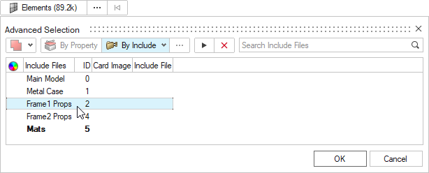
 to reverse or align Segment
directions using the Adjust Directions
dialog. The Reverse function flips all or some Segment
directions simultaneously. The Align function is only available
for Segments defined on shell elements.
to reverse or align Segment
directions using the Adjust Directions
dialog. The Reverse function flips all or some Segment
directions simultaneously. The Align function is only available
for Segments defined on shell elements.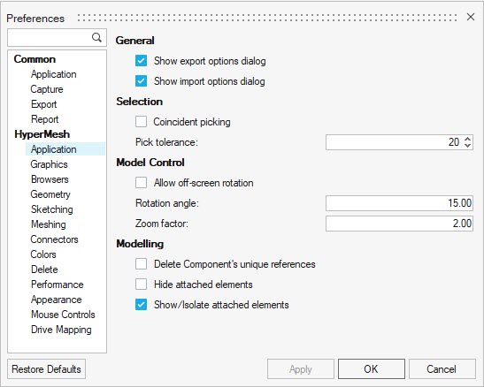
 in the Move tool
microdialog to replace the standard Move tool with a single normal
offset arrow. While in this mode, drag or click on the arrow to type a
normal offset value to move the nodes. Optionally, use the microdialog
buttons to review and edit the normals calculation options and area.
This mode is not available for nodes connected to 3D elements.
in the Move tool
microdialog to replace the standard Move tool with a single normal
offset arrow. While in this mode, drag or click on the arrow to type a
normal offset value to move the nodes. Optionally, use the microdialog
buttons to review and edit the normals calculation options and area.
This mode is not available for nodes connected to 3D elements.