comparisonunified
Defaults for the offset functionality of Model Verification.
GUI Default Settings
- tolerance
- Search tolerance for searching nearest parts as well as search tolerance for
finding matching entities.
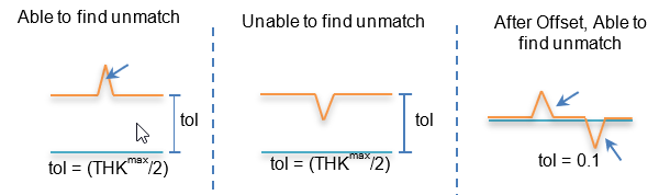
Figure 1. - threshold
- Percentage values for judging Identical, Partial Identical and Non-Identical parts. Multiple values are accepted. If the percentage value is less than the first value, it is considered a Non-Identical part. If the percentage is more than the last value, it is considered an Identical part. A low value such as 5% is not recommended for the first value when checking a large number of parts. Common examples are (30 60 90) and (60 99).
- base-directory
- Initial director for Base model.
- base-filetype
- Input model types.
- XML
- BOM file or UDMXML file saved from HyperMesh.
- CAD
- CAD geometry,1 part/file (folder contains multiple CAD).
- FE
- Solver Deck file (single file).
- Assembly
- CAD Assembly file (CatProduct/JT Assembly).
- Multiple Assembly
- Multiple Assembly files.
- Spot File
- Spot weld files (.vip, .mwf, .mcf, or .xml).
- variant-directory
- Initial director for Variant model.
- variant-filetype
- Input model types.
- XML
- BOM file or UDMXML file saved from HyperMesh.
- CAD
- CAD geometry,1 part/file (folder contains multiple CAD).
- FE
- Solver Deck file (single file).
- Assembly
- CAD Assembly file (CatProduct/JT Assembly).
- Multiple Assembly
- Multiple Assembly files.
- Spot File
- Spot weld files (.vip, .mwf, .mcf, or .xml).
- report
- Initial director for report out path.
- report option
- Output report formats. After the check is completed, you can change this option to generate the report any number of times. Excel report is faster than PowerPoint report.
- scope
- Output result types.
- Matched
- 30.0 (threshold) to 100% matched parts
- Unmatched
- 0.0 to 30% matched parts
- unmatched+partial
- Unmatched and Partially matched parts will be displayed in the Comparison report.
- Both
- 0.0 to 100% parts
- mode
- Default radio button options for Run type.
- interactive
- Checks will be run in the front ground HyperMesh session.
- background
- Checks will be executed in the background HyperMesh sessions, if error occurs recovery will be executed, the errors will be displayed in the browser as “Crash” keyword.
Comparison Settings
- imageType
- Output image types.
- .jpg
- Light weight 2D
- min-area
- Minimum area of the part to be considered for the comparison.
- Minimum-diagonal BBox
- Miminum parts bounding box diagonal distance to be considered for the comparison.
- Compare Thickness
- Compares thickness assigned on FE parts and displays unmatched thickness in report.
- FE Thickness Tolerance
- Allowable thickness variation while thickness compares.
- Quick Compare
- New comparison logic activated which imports base, variant model and performs comparison at once. Supports FEvsFE and CADvsFE. Result model displayed after comparison with match% legend.
- Export Unmatched
- Export unmatched surfaces to JT/Iges file. Supported for CAD vs CAD Comparison. Keeping the same CAD file name, DLT string is appended on the exported file.
- Result-file
- The name of the resulting file.
- Check elems in Surf Hole
- CAD holes vs FE holes are compared, displays if any mismatches in the
holes via comparison report.
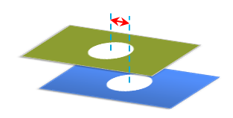
Figure 2. - Check
- Compares FE holes vs surface holes or surface holes vs FE holes.
- Min Dia of Hole
- The minimum hole diameter for checking the holes mismatch. Big diameter holes are taken care by default.
- Max Dia of Hole
- The maximum hole diameter for checking the holes mismatch.
- free-edge-check
- Compares free edge of FE data against free edges of CAD surface boundary
lines, mismatch will be displayed in the comparison report.
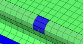
Figure 3. - free-edge-tolerance
- Free edges in FE data less than this tolerance will be ignored.
- find-cad-thickness
- Calculates thickness from cad by using Volume and Area of the CAD, the Thickness column will display the results. This calculated thickness value will be given preference over GUI tolerance for judging the match percentage.
- use-fe-thickness
- Thickness from FE data will be given preference over GUI tolerance for judging the match percentage.
- ignore fe-thickness
- Thick shell option will be deactivated to ignore thickness from FE and fins shapes mismatches only, applicable for CADvsFE.
- delete-fefiles
- Deletes the temporary FE folder created my MVD during the CAD-FE comparison. Once this folder is deleted, Result review may not be possible.
- bomcomparison
- Compares PID, PartName, PartNumber, MATERIAL, THICKNESS, and Revision values of a Part, except the shape. Reports are generated in both PowerPoint and Excel, the same as a normal comparison.
- contactcomparison
- Comparison of contact cards for the parts, it checks for card names and number of contact cards. Limited to Radioss, Nastran, PAM-CRASH, LS-DYNA.
- loadcomparison
- Comparison of Load collector cards for the parts, it checks for card names and number of contact cards. Limited to Radioss, Nastran, PAM-CRASH, LS-DYNA.
- remove-pinhold
- Removes small diameter in holes on CAD surface, applicable only on CAD-FE comparison.
- pinhold-radius
- Pin hole radius, holes less than this value will be physically removed while comparison.
- mesh-unmatched
- After comparison for unmatched parts below, the process is automatically
executed.
- Group parts based on match% and report threshold%
- Execute BatchMesher
- Replace CAD with Batch Meshed FEs
- Assign material and property
- Load assembly (old + new mesh) import
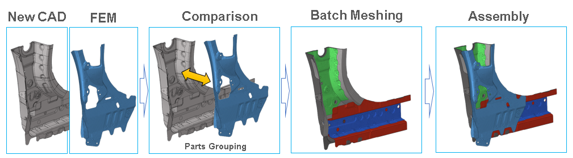
Figure 4. - Parts Group (Part Browser / Part Set View)
- partial-matches
- After comparison for the Partial Identical parts, meshing will be automatically executed. Identical areas will be retained and surfaces for the non-identical areas will be sent to meshing. Both the retained mesh and the new meshes are stitched together and added under the representation.
- mesh-unmatched-approach
- If Replicate, all surfaces are sent to meshing and the reused mesh will be imprinted to remove the overlapping areas (recommended for solid CAD). If Rebuild, unmatched surfaces alone are sent to meshing (recommended for surface CAD).
- cadtofeapproach
- Converts CAD data facets and performs comparison to capture feature level mismatches. Applicable to CADvsCAD compsrison.
- loopLimit
- Each time two parts will be compared if the value is 0. # of parts are loaded at once in one HyperMesh session and comparison will be executed, if the value is more than 0.
- samelocation
- Parts will be searched at the same location of the base part, along with
the tolerance value. Parts far from each other will be ignored. Works
fine with small offset between both parts.
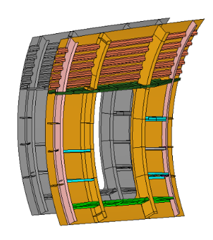
Figure 5. - translation
- Parts will be searched at the same location of the base part. If the
same shape part is not found, the variant part is translated, then
translated comparison will be executed. Translation distance will be
automatically calculated.
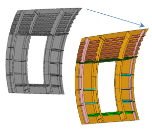
Figure 6. - symmetry
- Parts will be searched at the same location of the base part. If the
same shape part is not found variant part is reflected, then symmetry
comparison will be executed. Symmetry plane will be calculated by the
parameter below.
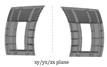
Figure 7. - symmetryPlane
- Plane to be considered for symmetryPlane comparison.
- auto
- Comparison will consider parts at same/translated/symmetry rotated locations. For CAD vs CAD, the match% and unmatched entities will reported, transformed matrix for base part will be exported in a .csv file. For other types, AI based comparison will be executed and only match% will be reported with (AI) tag. Auto option is turned ON, in addition to samelocation.
- AI-approach
- AI based comparison is executed in addition to the default topological comparison taking the best match. Applicable to Normal comparison and Quick-comparison Comparison Reports will display (AI) tag if the AI based results are reported.
Filters
- cgtolerance-distance
- Distance between centroid of base mode part and variant model part. Parts will not be compared if the parts centroid are more than this value. The recommended value is around 200mm.
- min-areapercent
- Minimum area ratio of base and variant parts. Parts will not be compared if the parts ratio is less than this value. The recommended value is around 60%.
- max-areapercent
- Maximum area ratio of base and variant parts. Parts will not be compared if the parts ratio is more than this value. The recommended value is around 140%.
- Part-Pair Check Attribute
- During the comparison, Parts that need to be compared can be filtered based on the below filters
- same-pid-only
- Parts with the same PID will be compared and Parts with different PIDs will be ignored if the value is ON. There is not much gain in the performance, but 1% match will be reported, in case this option is ON. This must be turned OFF in case not all the parts PID are not matching.
- same-partname-only
- Parts with the same PartName will be compared and Parts with different PartName will be ignored if the value is ON. This must be turned OFF in case not all the parts Name are not matching.
- compare-midsurf
- Solid CAD vs Mid Mesh comparison will happen if this value is ON. This will affect only CAD-FE only when CAD is solid or closed volume surface.
- seamtreatment
- Seam nodes are excluded from the unmatched percentage calculation. This must be turned OFF in case Seam welds are not used in FE model.
- bbox-view
- Bounding boxes for each part are displayed in the HyperMesh graphics for reference after the check and report is done. You can check if both of CAD or FE is at the same place or the same size.
Representation Comparison
- Check
- Single BOM comparison will be executed, if this parameter is ON, inside single part multiple representations will be compared and reports generated. Two model comparisons will be executed, if this parameter is OFF.
- base-reptypes
- Representations available in the Part Browser. CAD represents the Original CAD data, Mesh represents the FE data created by BatchMesher.
- Variant-reptypes
- Representations available in the Part Browser. CAD represents the Original CAD data, Mesh represents the FE data created by BatchMesher. Usually this can be Mesh or Common.
- Rep Comparison Output (stored in Report folder
-
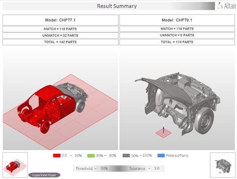
Figure 8.
Match-area
- cad-fe, cad-cad, fe-fe
-
- Matched
- Matched results will be calculated only if the entities are at the exact location.
- matched-overlapped
- Matched results will be the sum of matched and Overlapped entities.
- matched-overlap-intersected
- Matched results will be the sum of matched, Overlapped and Intersected entities.
- match-value
- Match % output type.
- round-off
- Match % display format.
Details on the Calculation Method
- Matched
- Occurs when a source or target surface is within the given tolerance of
a compared surface using a direct surface to surface comparison. All
points and lines comprising each surface must match between the
surfaces. Each matched surface is placed in a separate match type group
with the surface it matches.
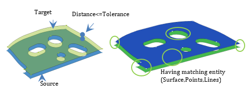
Figure 9. - Unmatched
- Occurs for surfaces and elements when the matched criteria are not met.
- Overlapped
- Occurs when all facet nodes of a source or target surface are within the
given tolerance of the compared surfaces and all of the facet nodes on
the nearest compared surfaces' exterior edges are within the given
tolerance of the source or target surface's exterior edges.
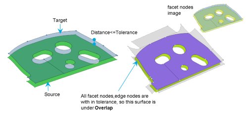
Figure 10. - Intersected
- Occurs when at least one but not all facet nodes on a source or target
surface are within the given tolerance of the compared surfaces or at
least one of the facet nodes on the nearest compared surfaces' exterior
edges is outside the given tolerance of the source or target surface's
exterior edges.
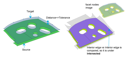
Figure 11.