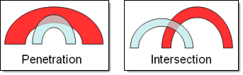
Penetration is defined as the overlap of the material thickness of shell elements,
while intersection is defined as elements that actually pass completely through one
another.
Figure 1. Penetration and Intersection
Restriction: Penetration checking is supported by all of the impact
solver interfaces, such as LS-DYNA, Radioss and PAM-CRASH, and
works best with a solver interface that supports thickness data for modeled
shell elements. The default HyperMesh solver
interface does not support modeled element thickness, but the penetration
checking tools can still be used to specify a uniform thickness when performing
a check.
You can only set up and initiate the check in the Penetration panel; the
majority of the checking tool actually resides in a special tab that opens
in the tab area. However, this tab only displays after you complete the
panel and run an initial check.
When the penetration check runs, it automatically masks (hides) everything
in your model except for the penetrating or intersecting elements. It then
fits the view to these elements’ components. You can show or hide additional
elements using toolbar buttons located in the Penetration tab, and you can
make other entity types, such as ellipsoids, visible again via the Display
panel or the Mask panel.
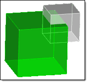
Solid entities never register penetrations between each other; instead, any
overlap between solids registers as intersections, because one or more of
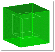
each the solid’s faces intersect. A solid that is completely contained
within another solid will not be detected as an intersection or penetration,
because its faces will not intersect any of the larger (containing) solid’s
faces. In addition, only surface elements register penetrations; the tool
cannot find penetrations between internal, that is, tetra- or hexa-,
elements.
Figure 2. Intersections Found
Figure 3. No Intersections
Solids can register penetrations with respect to adjacent shell elements,
based on the thickness of the shell elements.
From the Tools page, click Penetration.
Use the entity selector to select entities to be checked for penetrations or
intersections.
In any case, the penetrating elements will be found; for example, picking two
components locates elements from each component that penetrate elements of the
other.
Select the type of interferences to check for.
Choose all interferences, intersections
only, or penetrations
only.
Note: Solid entities only register penetrations in
conjunction with shell elements. With other solids, they only register
intersections.
Select the type of elements to check.
Choose 2D and 3D elements, 2D only
elements, or 3D only elements.
If you choose 2D only elements or 3D only
elements, HyperMesh only checks
elements of the specified type for penetration. Elements in the selected
entities which are not of that dimensional type will be ignored, even if
they penetrate or intersect another entity.
To enter a tolerance for penetration checking, select the allowable
interference depth checkbox.
For example, if you check a model of a part measured in millimeters, and are
not concerned about penetrations of less than a tenth of a millimeter, you
could set this field to a value of 0.1. The penetration tool would then
ignore any elements that penetrated each other by 1/10 of a millimeter or
less, but still locate and highlight elements with a penetration depth
greater than 1/10 mm.
Some solvers will not permit direct, adjacent contact between elements, for
example a penetration depth of exactly zero, with no space between elements.
For such solvers, you should set this field to any negative value, such as
-0.1. This allows the penetration tool to locate and display elements that
are exactly adjacent to one another as if they were penetrating each other,
so that you can use the penetration fixing tools to add some space between
them.
Select a method adjusting thickness.
Not available when you run the check on groups, because a group’s thickness is
defined by its control card.
Choose Component thickness to use the thickness
value specified in a component’s property card for each element within that
component.
Choose thickness multiplier to enter a value to
multiply the selected entities’ thickness by for purposes of the penetration
check. Fractional numbers are acceptable, but negative ones are
not.
Choose uniform thickness to enter a thickness
value.
This can be used to work around the lack of thickness
information in the default HyperMesh user
profile, or when working with models that do not have a thickness
specified.
You can also use this option to determine the proximity
between non-penetrating parts by specifying a thickness greater than the
minimum distance between the selected elements.
To check for components that intersect or penetrate themselves, for instance,
due to high curvature in the component, select the include self
interference checkbox.
This option is computationally intensive, therefore it is not recommend that
you use it when checking large numbers of elements for penetration.
Click check.
The selected components, elements, or groups are checked for penetration and/or
intersection. A message in the status bar displays the
percentage progress of each step in the check.
If for some reason you wish to abort a check, you can do so by right-clicking in the
graphics area and holding the button down. The exact length of time that you must
hold the button depends on the size and complexity of the check you are running; the
check will cancel once its completion percentage increments. When the check aborts,
the status bar turns red and displays a message stating that
the check was canceled.
Once the penetration/intersection check is
complete, view the results of the check and make adjustments.