Solid Map meshing is
a method that creates a mesh of solid elements in a solid geometric volume.
Solid Map
Meshing Multiple Solids
You can select multiple solids for solid map meshing provided that each individual
solid is in fact mappable. However, the meshing engine cannot always mesh every selected
solid in a single operation, even when all the selected solids display as
mappable.
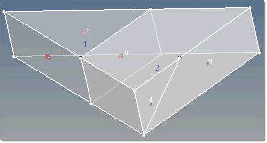
This may happen if the mappable constraints from different solids within the selection
contradict each other. For example, one type of mappable constraint is that certain
surfaces (along faces) of a mappable solid must be of the map-mesh type. When such
constraints are in conflict, faces that caused meshing to fail are marked with a red
square icon.
In Figure 1, both solids can be map-meshed individually, but solid 1 (the triangular one) must
have all of the marked faces (5, 6, and 9) map-meshed. This, however, causes a conflict
for solid 2, which can only be map-meshed by using the shared surface (6) as a
destination. This conflicts since this shared surface must match the meshes on surfaces
4 and 8 in order to mesh solid 2.
In such a case, you can mesh the remaining solids by deselecting the ones that are marked
with the red icon but retaining the others in your selection. This either allows you to
mesh the unmarked solids in a single action, or helps you further diagnose the problem.
The remaining solids, unfortunately, will require individual meshing or further
partitioning before they can be solid-map meshed as a group. Figure 1.
Partition Solids for Mappability
Before you can successfully solid mesh a model, ensure that the solids have been
partitioned so that they are either one directional or three directional
mappable.
Solid (3D) meshing can be done automatically, just like 2D shell meshing, but often
requires that complex parts be partitioned into groups of smaller, simpler,
connected solids instead of one large complex solid. In solid meshing, the ability
to be meshed is referred to as mappability.
Mappability is directional and can be likened to putting a surface mesh on one face
of the solid, then extending that mesh along a vector through the solid volume. So,
for example, a perfect cylinder is mappable in one direction, the axis between its
top and bottom faces, while a perfect cube is mappable in three, the axes between
each pair of its identical faces. However, a combustion engine's cylinder head
consisting of two cylinders of different radius joined together into a single solid
entity would need to be partitioned to divide the two cylinders. Once partitioned,
each cylinder would become mappable in one direction.
Note: Even when all partitioned
sections of the solid are mappable, this does not necessarily mean that they can
all be meshed at once. In some cases they may need to be meshed a few at a time,
or even individually in extreme cases. Mappability only ensures that the
partitioned section can be meshed.
Use the Mappable visualization mode to review solid partitioning for mappability. The
“Mappable” mode color codes the solids within the model according to whether the
solids are solid meshable. The ignored map, not mappable, 1 directional map, and 3
directional map all relate to the mappable state of the solids.
Tip: Change the color coding for the mappable state from the Options panel, Colors
subpanel.
When reading in a new model with solids, the model will be colored blue after you
activate the Mappable visualization mode, which indicates that the mappability is
currently being ignored. It is then necessary to partition the model so that the
state of the solids changes to 1 directional or 3 directional.
Note: If the model
does not include any solids, for example, only surfaces are present, you can use
the Solids panel on the Geom page to create solids from the surfaces.
If
some partitioning has already occurred from a previous session when the
.hm file has been read in
with the Mappable visualization mode already active, it will still be displayed as
"ignored" map. To invoke the mappable algorithm calculation, change to another
visualization mode, such as By Topo and then change back to Mappable again. This
recalculates the state of all solids within the model.
From the Visualization toolbar, set the geometry visualization mode to
Mappable.
The solid is color codes according to its mappability state.
Blue
Solid has not been edited, and therefore cannot evaluated for
mappability.
Orange
Solid has been edited, but remains completely unmappable (further
partitioning may enable mapping).
Yellow
Solid is mappable in 1 direction.
Green
Solid is mappable in three directions. This is very rare.
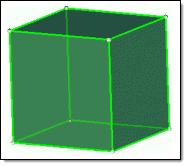
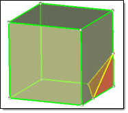
Figure 2. . The first cube is mappable in 3 directions, but if a corner is split
off it becomes mappable in only 1 direction, and the corner is not
mappable without further partitioning.
Partition solids for mappability.
Any solid edit operation will update the display of the solid entities
automatically.
Partitioning Solids for Mappability
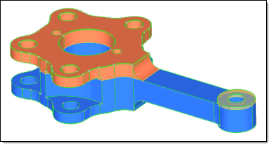
Figure 3
shows that one trim of the model by a single surface (the top surface of the
rectangular shaft, in this case) has created two additional solids within the model.
One solid remains in the ignored map state (blue), one is now not mappable (orange)
and one is one directional mappable (yellow - transparent).
Figure 3.
After additional partitioning the model using the tools found in the Solid
Edit panel, the model has transformed from having an ignored map and non-mappable
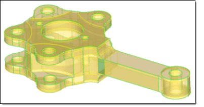
states to having only one directional and three directional mappable states. Figure 4 shows one three directional mappable solid, as
indicated by the green transparent solid at the base of the shaft where it joins the
part's main body. Figure 4.
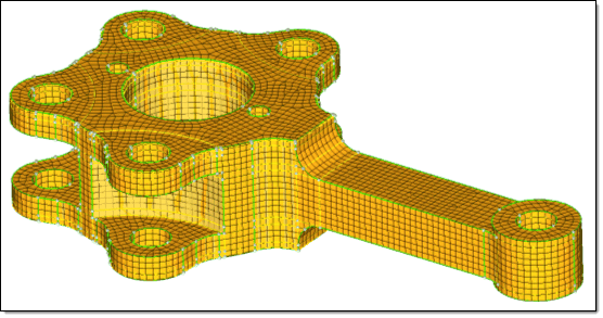
Once partitioning is successful, meshing can commence. Accessing the
Multi-Solids subpanel and selecting all of the solids, plus the required meshing
options, yields a complete 3D mesh for the entire complex part, as shown in Figure 5. Figure 5.
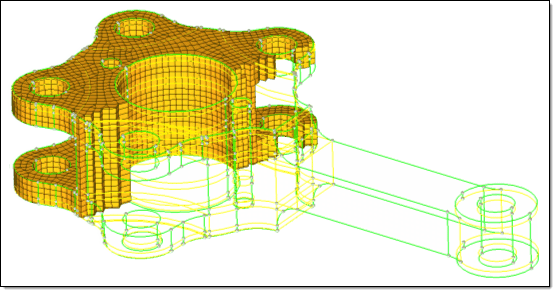
Selecting and masking a section of the elements confirms that the mesh is a
complete 3D mesh, as opposed to just a surface mesh, as shown in Figure 6. Figure 6.
Create Solid Map Mesh
Before you being, ensure that the solids have been partitioned so that they are
either one directional or three directional mappable. Refer to, Partition Solids for Mappability.
Also, make sure you have an existing 2D mesh, which will be used to extrapolate the
3D solid map mesh.
This topic uses the General subpanel, but the Line Drag, Linear Solid, and Ends Only
subpanels all draw from the same set of input controls. The Line Drag, Linear Solid,
and Ends Only subpanels panels simply filter out the controls that do not apply to
their mapping techniques.
Use the Line Drag subpanel to select a 2D mesh, and then select a line from
the model geometry to use as the mapping direction.
Use the Linear Solid subpanel to select two existing 2D meshes and
extrapolate a 3D mesh that connects them.
Use the Ends Only subpanel to select two opposing surfaces and one 2D mesh,
then extrapolate the mesh between the surfaces.
You can omit the source, the destination, or the along geometry by setting either one
of the entity selectors to (none). Only one of these selections can be set to
(none); the other two selections are then required to define the volume to fill.
From the 3D page, click solid map.
Select the General subpanel.
For source geom, select a geometry type and then select the source geometry
that defines the source face of the 3D volume.
Choose surfs to select surfaces that define the
source face of the volume/solid.
Choose lines to select lines that define the
periphery of the source face.
Choose nodes to select multiple lists of nodes,
each representing the periphery of the source face.
Choose none if you do not want to define source
geometry. The geometry inferred from the elems to drag is considered as
source geometry.
Use the elems to drag selector to select the elements/mesh that correspond to
the source face extruded to create the solid mesh.
For dest geom, select a geometry type and then select the destination geometry
that defines the destination face of the 3D volume.
Choose surfs to select surfaces that define the
destination face of the volume/solid.
Choose lines to select lines that define the
periphery of the source face.
Choose nodes to select multiple lists of nodes,
each representing the periphery of the source face.
Choose none if you do not want to define
destination geometry.
Select elems to match.
Choose elems to select elements on the
desitnation surface that you wish the 3D mesh to match up with.
Choose none to access the smooth dest checkbox,
which when selected, smooths the mesh that is mapped on the destination face
when your destination geometry varies greatly from the source
geometry.
For along geom, select a geometry type and then select the geometry that
defines the face of the 3D volume along which you wish to map the mesh.
Choose surfs to select surfaces to define the
mapping face of the volume/solid.
Choose lines to select lines that define the
periphery of the source face.
Choose nodes to select a node list that defines a
line along which to map.
Choose mixed to select any combination of
surfaces, lines, 2D elements/shell faces, and/or nodelist/nodepath. When
elements are used, the mapped solid mesh maintains the nodal positions with
selected elements. They can be equivalenced to have common nodes. While
selecting nodelist/nodepath, each selection should represent an edge that
connects the source and destination.
Choose none if you do not want to define
geometry.
For along parameters, define the parameters required for the mesh along the
solid map.
This determines the number of elements along the depth of the mapping. If the
size or density is set to "0", the element size/density is calculated based
on the average element size of the source elements (elems to drag).
For along bias style, choose the type of biasing to use while creating nodes in
the along direction.
The biasing style works in conjunction with biasing intensity. If intensity
is "0", biasing is not applied.
In the intensity field, enter a biasing intensity.
Click mesh.
HyperMesh displays the progress of the solid map meshing process in
the status bar. Upon completion, HyperMesh
displays a report of the mesh quality. The element quality value reported is the
worst scaled Jacobian in the mesh. The scaled Jacobian's value may range from 0.0 to
1.0(best). An elem's scaled Jacobian is a ratio of the elem Jacobian over the
Jacobian of an ideal elem of the same configuration.
Create Solid Map Mesh from One
Volume
Create a new 3D mesh from a single, mappable solid volume.
Before you being, ensure that the solids have been partitioned so that they are
either one directional or three directional mappable. Refer to, Partition Solids for Mappability.
Also make sure you have an existing 2D mesh, which will be used to extrapolate the 3D
solid map mesh. When creating mesh from the One Volume subpanel, a 3D mesh can be
automatically created directly on solids as long as the solids you select are
already mappable.
From the 3D page, click solid map.
Select the One Volume subpanel.
For volume to mesh, select the solid/surface to mesh.
Define the direction of mesh mapping.
For source hint, select the “beginning” surface.
For dest hint, select the “ending” surface.
For source shells, select the type of elements to use when creating the
resulting output solid mesh.
This defines the 2D mesh on the initial surface of the solid, and will
dictate the output element type when meshing the solids.
Choose mixed to use hexa and penta
elements.
Choose quad to create hexa elements.
Choose trias or R-trias to
create only penta elements (right-angle pentas in the case of
R-trias).
Select which component to put the newly-created elements.
Choose elems to solid/surf comp to organize
elements in the same component that contains the solid and its
surfaces.
Choose elems to current comp to organize new
elements in the current component.
To smooth the elements on the resulting face of the solid to improve the
resulting mesh quality, select the smooth dest
checkbox.
For along parameters, define the parameters required for the mesh along the
solid map.
This determines the number of elements along the depth of the mapping. If the
size or density is set to "0", the element size/density is calculated based
on the average element size of the source elements (elems to drag).
For along bias style, choose the type of biasing to use while creating nodes in
the along direction.
The biasing style works in conjunction with biasing intensity. If intensity
is "0", biasing is not applied.
In the intensity field, enter a biasing intensity.
Click mesh.
HyperMesh displays the progress of the solid map meshing process in
the status bar. Upon completion, HyperMesh
displays a report of the mesh quality. The element quality value reported is the
worst scaled Jacobian in the mesh. The scaled Jacobian's value may range from 0.0 to
1.0(best). An elem's scaled Jacobian is a ratio of the elem Jacobian over the
Jacobian of an ideal elem of the same configuration.
Create Solid Map Mesh from
Multiple Solids
Create a new 3D mesh from multiple, mappable solids.
Before you being, ensure that the solids have been partitioned so that they are
either one directional or three directional mappable. Refer to, Partition Solids for Mappability.
Also make sure you have an existing 2D mesh, which will be used to extrapolate the 3D
solid map mesh. When creating mesh from the Multi Solids subpanel, a 3D mesh can be
automatically created directly on solids as long as the solids you select are
already mappable.
From the 3D page, click solid map.
Select the Multi Solids subpanel.
Use the solids selector to select the desired solids.
Define the direction of mesh mapping.
For source hint, select the “beginning” surface.
For dest hint, select the “ending” surface.
Select the meshing mode.
Choose automatic to automatically create the 3D solid mesh.
Choose interactive to manually define mesh density and element mesh
patterns before creating a final mesh.
In the elem size field, enter the size to be used when initially distributing
the nodes to the edges.
For source shells, select the type of elements to use when creating the
resulting output solid mesh.
This defines the 2D mesh on the initial surface of the solid, and will
dictate the output element type when meshing the solids.
Choose mixed to use hexa and penta elements.
Choose quad to create hexa elements.
Choose trias or R-trias to create only penta elements (right-angle
pentas in the case of R-trias).
Select which component to put the newly-created elements.
Choose elems to solid/surf comp to organize elements in the same
component that contains the solid and its surfaces.
Choose elems to current comp to organize new elements in the current
component.
To smooth the elements on the resulting face of the solid to improve the
resulting mesh quality, select the smooth dest
checkbox.
To keep the solid elements generated more perpendicular to the surface faces in
the along direction, select the apply orthogonality to
along checkbox.
To halt the meshing routines upon the creation of a bad jacobian solid element,
select the stop meshing on bad jacobian checkbox.
To force the mesh to honor any prior edge node density settings when creating
the temporary surface mesh, select the previous settings
checkbox.
Click mesh.
If the automatic mesh mode is selected, a solid mesh is created. If
interactive mesh mode is selected, temporary 2D shell meshes are created and the
node seeding density is assigned to all of the along edges and the Density
subpanel opens.