Model, local and volume selector mesh controls for volume meshing.
Model
Model mesh controls define boundary layer and/or tetrameshing parameters.
BL + Tetra
BL + Tetra model mesh controls define boundary layer and tetrameshing parameters.
Entity Selection Parameters
In the Entities field, use the entity selector to select the entities
that the mesh control applies to.
The following entities can be selected using the entity selector:
Components
Elements
Regions (solid selection only)
Solids
Note: If you have changed your selection to solid or region in
model volume mesh controls, existing local controls that have
elements or components selected will be made inactive. Any new local
mesh controls will have surfaces set for their default
selection.
If regions are selected, final volume mesh controls
will be placed in a component with the same name as the
region.
Meshing will only work if surfaces or solids have
mesh associated with them.
Boundary Layer Parameters
Available parameters vary depending on the Method you select: Simple,
Advanced, User Defined. For Simple and Advance mesh controls, refer to
Link to CFD Tetramesh Panel.
Table 1. Parameters
Parameter
Description
Basic Surface Mesh Treatment
Fixed
Prohibit selected elements from being
modified.
Float
Enable 2D base elements to be modified, if
necessary. Generally 2D base elements with NoBL
are modified when refinement zones are defined
and/or when the BL imprints on them.
BL Definition
When enabled, parameters will be editable and
will be applied to all selections. When disabled, a
BL definition will not be applied at model
level.
Local controls will override the BL
definition at the model level.
First Layer Thickness
Specify the thickness of the first boundary
layer.
First Layer Thickness Method (A)
Constant
Enable a constant thickness to be defined for
the first boundary layer of the selection.
As Factor of Base 2D Elements
Enable a factor, which will be multiplied by
the average element size, to be defined. The first
layer height for each element equals the average
element size multiplied by the factor. This option
is useful when the size of 2D elements varies
significantly and a constant first layer height is
not needed. With this factor, a smooth BL to
tetramesh transition for all elements can be
achieved.
Figure 1. First Layer Thickness Method (A)
Growth Rate
Determine how rapidly elements can increase in
size as they are created further and further away
from features. Figure 2. Growth Rate
Elements further from the features grow larger
with each row.
BL Growth Rate Method (A)
Constant
Enable a constant ratio to be defined, which
determines how boundary layers grow.
Acceleration
Enable a growth acceleration for boundary
layers to be defined beyond the first few layers.
This option acts as a growth rate on the growth
rate, but only after the first few initial
boundary layers. A Start Acceleration from Layer
must be defined first, and then from that layer
the acceleration will be started. An Acceleration
to the initial growth rate and a Maximum Growth
Rate must also be defined.
By default, the first two boundary layers grow
by the growth rate described above. However,
subsequent layers grow by the growth rate
multiplied by the acceleration factor. Thus, if d
is the initial thickness, r is the initial growth
rate, and a is the acceleration rate, then the
thicknesses of the successive layers are d, d*r,
d*r*(r*a), d*r*(r*a)^2, and so on.
Aspect Ratio Based
Enable the growth rate definition for boundary
layers to be based on the defined aspect ratio of
the final layer. After the first few initial
boundary layers, if this type of growth rate
method is selected, the rest of the BL will grow
to achieve the user defined Final layer height /
base ratio.
BL Thickness Control (UD)
Enable this option to enter either the Number of
layers or the Total BL thickness.
Second Group (UD)
Help to get a smooth transition between BL layers
and the tet core more quickly, by defining a higher
growth rate.
Final Layer Height/Base Ratio
Define the ratio between the total boundary layer
thickness and the average element size of the base
surface elements.
BL Stopping Criteria (A)
Determine what to do when BL has reached the
defined criteria for Final Layer Height/Base
Ratio.
Chop Off Layers
Chop off the BL if elements reach the aspect
ratio criteria.
Keep Growing Gr=1
Allow the BL to grow until the neighboring
elements begin to grow, even if elements reach the
aspect ratio criteria with GR =1.
Number of Layers (S)
Define the total number of layers to be generated
using the specified first layer thickness and growth
rate.
Hexa Transition Mode
Simple Pyramid
Transition from a BL hexahedral’s quad face to
a tetrahedral core mesh using one pyramid element.
The height of pyramid elements is controlled by a
simple transition ratio parameter, which
represents the ratio between the transition
pyramid height and the characteristic size of the
base quad.
All Prism
Split quad elements in the surface mesh into
two trias each so that there will be no need to
transition from quad faces to tria faces when
transitioning from the last boundary layer to the
tetrahedral core. This mode is very important when
there are quad elements on areas with (low)
distributed BL thickness ratios, because in such
areas the thickness of the transition elements,
for example simple pyramid, was not taken into
account when doing the interference study to
assign distributed BL thickness ratio to those
elements.
All Tetras
Generate tetra elements only in the boundary
layer and splits the quad elements of the surface
mesh into tria elements.
Boundary Layer Only
Generate only the boundary layer, stopping before
the tetrahedral core is generated. Adjacent surface
meshes are also modified to reflect changes
introduced by the boundary layer thickness. A
collector named ^CFD_trias_for_tetramesh is created
and is typically used to generate the inner core
tetrahedral mesh using the Tetramesh parameters
subpanel.
Boundary layer elements are placed in
a collector named CFD_boundary_layer; core
tetrahedral elements are placed in a collector
named CFD_Tetramesh_core. Both collectors are
automatically created if they do not exist.
However, if these collectors do exist, it is
recommended that you empty them before meshing;
otherwise there will be more than one set of
elements occupying the same physical volume. If
you mesh the volume in several steps (multi-volume
meshing), it is recommended that you empty the
collector before generating the mesh for the next
adjacent volume.
Core Mesher Parameters
Available options will direct how the core domain should be meshed. All
options will also rely on option in “Tetra Mesh” section.
Table 2. Parameters
Parameter
Description
Core Mesh
Tetra Mesh
Will create tetra mesh in core.
Hex Dominant
Will create hex elements in core and create
pyramids/tetrahedral in transition region. All
elements will have conformal connectivity.
Core Hex elements will be created based on
user defined Hexa Size. Height of tetra/pyramid
transition region can be controlled using Tet-core
Layer Height Factor.
Octree Dominant
Will create octree elements in core and create
pyramids/tetrahedral in transition region. All
elements except core octree elements will have
conformal connectivity.
Core Octree elements will be creates based on
user defined Max Octant Size and Min Octant Size.
Height of tetra/pyramid transition region can be
controlled using Tet-core Layer Height
Factor.
Figure 3. Core Octree Element
Hexa Size
Size of the hex mesh.
Enable Hexa Transition
When checked, allows you to generate a variable
size hex mesh with transition.
Minimal Hexa Size
The minimum size of the hex generated around the
boundary.
Tetra Mesh Parameters
The tetramesher is multi-threaded and will utilize available threads for
meshing similar. This behavior is similar to that of boundary layer
meshing.
Table 3. Parameters
Parameter
Description
Element Size Limits
Specify the average, minimum, maximum, or
minimum/maximum size of the tetramesh.
None
The maximum element size will be determined by
the input 2D elements size and growth rate.
Average Size
Enter the average element size for the
tetramesh. If you enter 10, the element sizes will
range between 6.6 and 14.
Maximum Size
Tetra element will not be above this
size.
Minimum Size
Tetra elements will not be below this
size.
Minimum/Maximum Size
Tetra elements will not be below or above this
size.
Minimum Height
Generate tetramesh with a minimum height above
the value defined. The tetramesh algorithm will
try to enforce the user-defined minimum
height.
Minimum Height/Maximum Size
Tetra elements will not be below or above this
height.
Maximum element size guidelines:
When the input shell element size is close to
the user defined maximum tetra size, then the
maximum tetra size is used in averaged sense
(therefore the actual maximum size may be larger
than defined). This prevents a large number of
elements from being created.
When the input shell element size is
sufficiently different then the user defined
maximum tetra size, the maximum size will be
enforced.
Quality
Normal
Use the standard tetra-meshing algorithm.
Optimize Speed
Use an algorithm for faster meshing. Use this
option if element quality considerations are less
important than mesh generation time.
Optimize Quality
Spend more time optimizing element quality,
and employs the volumetric ratio, or CFD skew
measurement for tetras as a quality measure. Use
this option if your solver is sensitive to element
quality.
Tetra Mesh Method
Select a tetra mesh method:
Delaunay
Enable a mesher, which is implemented based on
the delaunay approach. This method is recommended
for improved performance.
Advancing Front
Enables the legacy tetra mesher.
Octree Based
Enable an octree structured based
tetrameshing. Smoothing near boundaries will be
performed with this method.
Growth Rate
The Growth rate parameter works as follows: if d
is the initial thickness and r is the initial growth
rate, then the thicknesses of the successive layers
are d, d*r, d*r^2, d*r^3, d*r^4, and so on.
If
element quality is important and you are not
concerned with the total number of elements being
created, then Interpolate will produce the best
results because the element size changes smoothly
and therefore the element quality is
better.
Different default values are
specified for the various growth rate options:
Standard
1.2
Aggressive
1.35
Gradual
1.08
Interpolate
1.08
User Controlled, Octree based, Delaunay
Define your own value when you select this
option.
Tetramesh Height Factor Near Boundary
The Delaunay method allows options to control the
height of tetra mesh near boundary. Tetra transition
from boundary layer or surfaces can be controlled
using this factor. Figure 4. Height Factor = 1 Figure 5. Height Factor = .5
Pyramid Transition Ratio
Define the relative height of pyramid elements
used for the transition from hexa elements in the
boundary layer to the tetra elements in the
core.
Smoothing
Apply an extra stage of calculation to improve
overall mesh quality. Additional smoothing and
swapping steps will be performed and tetra elements
will be split to achieve a smoother mesh transition.
If tetra elements are used in the boundary layer,
then those elements will be excluded from smoothing
to maintain the original distribution.
Use Number of Layers
Define the number of tetrahedral layers to
generate.
When enabled, the Tetramesher ensures the
tetracore contains, at minimum, the specified
number of tetra layers in the model. This
functionality ensures a certain mesh resolution in
case of close proximity or thin channels.
When generating multiple tetrahedral layers, keep
the following restrictions in mind:
Do not generate more than three or four
layers, unless you refine the surfaces to have a
fine mesh at close proximity areas.
Layer meshes will not be created near narrow
strip surfaces, as the current algorithm does not
alter the surface mesh given.
Advanced Parameters
Table 4. Parameters
Parameter
Description
Boundary Layer
Propagation
Treatment at Sharp Edges
Node collapse
Collapse BL at baffles or sharp corners below
the defined angle. Figure 6. Node Collapse. The baffle is colored yellow.
Multiple normal
Grow multiple normals around baffles or sharp
corners below the defined angle. If two adjacent
elements enclose an angle smaller than the
threshold (sharp edge pointing into the volume),
normals will be computed on that edge and the
boundary layer will consider those normals. Figure 7. Multiple Normal. The baffle is colored yellow.
Entities
If multiple normal option is selected, select
lines or nodes on which the multiple normal BL needs
to be created. If there is no selection and multiple
normal option is selected, it will consider features
defined by "Sharp edge angle". You can define any
angle.
Sweep Angle
If multiple normal option is selected, sweep
angle will define number of BL segments created at
defined feature edge. The number of BL segments at
the defined edge = 180 / sweep angle. BL is smoother
with smaller angles.
Sharp Edge Angle
Define the threshold of angles below which the BL
should be collapsed.
Auto append neighboring edges
If on, automatically append the neighboring
selection to avoid early termination of BL.
Minimum Imprint Angle from BL to Non-BL
Control which cases to imprint BL entities on
without BL components. If the angle between the BL
component and the non BL component is high,
imprinting will create high aspect ratio elements.
If the angle between BL and Non-BL entities
(component elements) is less than the imprint angle
or greater than (180-imprint angle), then the BL
will collapse rather than imprinting on non-BL
entities.
Recommended range: 6-10
Max Layer Difference Between Neighbors
Control the maximum layer difference between
neighboring elements. This parameter helps avoid
situations where all BLs collapse at once, and also
provides smooth BL transitions in cases of BL
truncation. A good value for this parameter is 1/4
of the total BL layers. The value specified also
depends on layer height.
Recommended range:
Depends on how many layers you are
growing.
Proximity
Maximum BL Compression
Enable BL compression, or squeezing, when there
is not enough space available for the BL to grow.
The BL will try to compress by the max BL
compression factor first. For example, if the
original total BL height is defined as 1, with a 0.4
max BL compression, the BL layers will try to be
compressed until 0.6 of the total height is reached.
Once the BL is compressed to this value, the mesher
will start chopping off layers if there is not
enough space.
A value of zero enforces no BL
compression, which is useful when you want to
maintain the BL height; a value of one enables the
maximum possible compression.
Recommended
range: 0-0.6
Minimum BL Thickness/Base Ratio
Due to close proximity, the BL will sometimes
only be able to generate one to two layers (a very
small total BL height at that location). At that
location, it might be possible that the transition
between BL layers and the tetra core is bad. With
this factor, if the total BL height is less than the
defined factor base size, all of the BL layers will
be chopped off.
By default, this value is zero,
which disables the effects of this
parameter.
Minimum Tetcore/Final Layer Height Ratio
Control the minimum height of the tet core as a
factor of the final layer height.
After creating
the BL in close proximity, there will be a small
space available for tetramesh. This results in
high aspect ratio tetra elements.
Recommend
value: 1.3 (default)
Boundary Layer
Quality
Generation Method
Controls the growth of boundary layers.
Optimize Quality
Use a set of meshing parameters, which ensures
a good quality boundary layer in most cases.
Optimize Speed
Choose meshing parameters in a way that the
meshing time is minimized and an acceptable
boundary layer quality is achieved.
Maximum Cell Skewness
Chop off BL cells exceeding the defined maximum
cell skewness. This parameter prevents the
generation of highly skewed elements.
The tetra
mesher sometimes creates better quality elements
compared to the BL mesher. If your input 2D mesh
has bad element quality and topology, it is
recommended that you define a higher value.
Recommended range: 0.8 - 0.95
Minimum Normalized Jacobian
Chop off BL cells exceeding the defined minimum
normalized Jacobian. This parameter prevents the
generation of negative elements.
Recommended
range: 0.05 - 0.2
Tetra Quality
Element Quality Target
Select an element criteria and threshold. After
the tetrameshing step, a mesh optimization step will
be performed to fulfill the defined threshold for
the selected element criteria.
Available quality
criteria include: Volume Skew, Tetra Collapse, and
Cell Squish.
Volume Setup
Validate 2D Input
Check BL elements before tetrameshing to rectify
if there is anything wrong with the input
(intersecting elements) provided for the
tetramesh.
Fix Invalid 2D Element
Fix invalid elements (at present only
unoffsettable nodes) before volume meshing.
For
unoffsettable nodes (where BL collapses if not
smooth), the connected elements will be smoothed
where the BL will be generated.
Fix Component Boundaries
Anchor nodes are maintained during CFD
tetrameshing, so that the new mesh adheres to them.
1D elements can be selected instead of nodes if you
need a tetra element edge at a certain location.
Select this option when certain mesh nodes or edges
are required on a certain location, such as for
post-processing purposes.
If the Float option is
selected for some boundary regions, surface shell
edges will be swapped during mesh generation.
However, this prevents the swapping of edges
between two components. Figure 8.
Update Input Shells
Automatically update the shells on all boundaries
after meshing. Updated shell elements are placed in
the initial boundary shell components.
Fill Void
Mesh all volumes. If your geometry includes
volumes inside of another volume, enable this
parameter.
For example, if you had a sphere
inside of a larger sphere, enabling this parameter
would cause the volume of the inner sphere as well
as the volume between the two spheres to be
meshed.
Other
Anchor Node
Node that will remain and be re-used in the new
mesh. Anchor nodes are "fixed" so that the
automesher cannot move or replace them; in essence,
they are exceptions to the re-meshing operation, and
the new mesh must utilize them.
In the Entities field, use the entity selector to select the entities
that the mesh control applies to.
The following entities can be selected using the entity selector:
Components
Elements
Regions (solid selection only)
Solids
Note:
If you have changed your selection to solid or region in model
volume mesh controls, existing local controls that have elements
or components selected will be made inactive. Any new local mesh
controls will have surfaces set for their default selection.
If regions are selected, final volume mesh controls will be
placed in a component with the same name as the region.
Meshing will only work if surfaces or solids have mesh associated
with them.
Tetra Mesh Parameters
Table 5. Parameters
Parameter
Description
Base Surface Mesh Treatment
Fixed
Prohibit selected elements from being
modified.
Float
Modify 2D base elements, if necessary.
Generally 2D base elements with NoBL are modified
when refinement zones are defined and/or when the
BL imprints on them.
Element Size Limits
Specify the average, minimum, maximum, or
minimum/maximum size of the tetramesh.
None
The maximum element size will be determined by
the input 2D elements size and growth rate.
Average Size
Enter the average element size for the
tetramesh. If you enter 10, the element sizes will
range between 6.6 and 14.
Maximum Size
Tetra element will not be above this
size.
Minimum Size
Tetra elements will not be below this
size.
Minimum/Maximum Size
Tetra elements will not be below or above this
size.
Minimum Height
Generate tetramesh with a minimum height above
the value defined. The tetramesh algorithm will
try to enforce the user-defined minimum
height.
Minimum Height/Maximum Size
Tetra elements will not be below or above this
height.
Maximum element size guidelines:
When the input shell element size is close to
the user defined maximum tetra size, then the
maximum tetra size is used in averaged sense
(therefore the actual maximum size may be larger
than defined). This prevents a large number of
elements from being created.
When the input shell element size is
sufficiently different then the user defined
maximum tetra size, the maximum size will be
enforced.
Quality
Normal
Use the standard tetra-meshing algorithm.
Optimize Speed
Use an algorithm for faster meshing. Use this
option if element quality considerations are less
important than mesh generation time.
Optimize Quality
Spend more time optimizing element quality,
and employs the volumetric ratio, or CFD skew
measurement for tetras as a quality measure. Use
this option if your solver is sensitive to element
quality.
Tetra Mesh Method
Select a tetra mesh method:
Delaunay
Enable a mesher, which is implemented based on
the delaunay approach. This method is recommended
for improved performance.
Advancing Front
Enables the legacy tetra mesher.
Octree Based
Enable an octree structured based
tetrameshing. Smoothing near boundaries will be
performed with this method.
Growth Rate
The Growth rate parameter works as follows: if d
is the initial thickness and r is the initial growth
rate, then the thicknesses of the successive layers
are d, d*r, d*r^2, d*r^3, d*r^4, and so on.
If
element quality is important and you are not
concerned with the total number of elements being
created, then Interpolate will produce the best
results because the element size changes smoothly
and therefore the element quality is
better.
Different default values are
specified for the various growth rate options:
Standard
1.2
Aggressive
1.35
Gradual
1.08
Interpolate
1.08
User Controlled, Octree based, Delaunay
Define your own value when you select this
option.
Tetramesh Height Factor Near Boundary
Delaunay method allow option to control height of
tetra mesh near boundary. Tetra transition from
boundary layer or surfaces can be controlled using
this factor. Figure 9. Height Factor = 1 Figure 10. Height Factor = 0.5
Pyramid Transition Ratio
Define the relative height of pyramid elements
used for the transition from hexa elements in the
boundary layer to the tetra elements in the
core.
Smoothing
Apply an extra stage of calculation to improve
overall mesh quality. Additional smoothing and
swapping steps will be performed and tetra elements
will be split to achieve a smoother mesh transition.
If tetra elements are used in the boundary layer,
then those elements will be excluded from smoothing
to maintain the original distribution.
Use Number of Layers
Define the number of tetrahedral layers to
generate.
When enabled, the Tetramesher ensures the
tetracore contains, at minimum, the specified
number of tetra layers in the model. This
functionality ensures a certain mesh resolution in
case of close proximity or thin channels.
When generating multiple tetrahedral layers, keep
the following restrictions in mind:
Do not generate more than three or four
layers, unless you refine the surfaces to have a
fine mesh at close proximity areas.
Layer meshes will not be created near narrow
strip surfaces, as the current algorithm does not
alter the surface mesh given.
Hexa Size
Size of the hex mesh.
Enable Hexa Transition
When checked, allows you to generate a variable
size hex mesh with transition.
Minimal Hexa Size
The minimum size of the hex generated around the
boundary.
Advanced Parameters
Table 6. Parameters
Parameter
Description
Tetra Quality
Element Quality Target
Select an element criteria and threshold. After
the tetrameshing step, a mesh optimization step will
be performed to fulfill the defined threshold for
the selected element criteria.
Available quality
criteria include: Volume Skew, Tetra Collapse, and
Cell Squish.
Volume Setup
Validate 2D Input
Check BL elements before tetrameshing to rectify
if there is anything wrong with the input
(intersecting elements) provided for the
tetramesh.
Fix Invalid 2D Element
Fix invalid elements (at present only
unoffsettable nodes) before volume meshing.
For
unoffsettable nodes (where BL collapses if not
smooth), the connected elements will be smoothed
where the BL will be generated.
Fix Component Boundaries
Anchor nodes are maintained during CFD
tetrameshing, so that the new mesh adheres to them.
1D elements can be selected instead of nodes if you
need a tetra element edge at a certain location.
Select this option when certain mesh nodes or edges
are required on a certain location, such as for
post-processing purposes.
If the Float option is
selected for some boundary regions, surface shell
edges will be swapped during mesh generation.
However, this prevents the swapping of edges
between two components. Figure 11.
Update Input Shells
Automatically update the shells on all boundaries
after meshing. Updated shell elements are placed in
the initial boundary shell components.
Fill Void
Mesh all volumes. If your geometry includes
volumes inside of another volume, enable this
parameter.
For example, if you had a sphere
inside of a larger sphere, enabling this parameter
would cause the volume of the inner sphere as well
as the volume between the two spheres to be
meshed.
Other
Anchor Node
Node that will remain and be re-used in the new
mesh. Anchor nodes are "fixed" so that the
automesher cannot move or replace them; in essence,
they are exceptions to the re-meshing operation, and
the new mesh must utilize them.
Local
Local mesh controls define regions where boundary layers are desired, or are not
desired.
No BL
No BL local mesh controls define components/elements on which boundary layers mesh is
not required.
Entity Selection Parameters
In the Entities field, use the entity selector to select the entities
that the mesh control applies to.
The following entities can be selected using the entity selector:
Components
Elements
Regions (solid selection only)
Solids
Note:
If you have changed your selection to solid or region in model
volume mesh controls, existing local controls that have elements
or components selected will be made inactive. Any new local mesh
controls will have surfaces set for their default selection.
If regions are selected, final volume mesh controls will be
placed in a component with the same name as the region.
Meshing will only work if surfaces or solids have mesh associated
with them.
Boundary Layer Parameters
Table 7. Parameters
Parameter
Description
Basic Surface Mesh Treatment
Fixed
Prohibit selected elements from being
modified.
Float
Enable 2D base elements to be modified, if
necessary. Generally 2D base elements with NoBL
are modified when refinement zones are defined
and/or when the BL imprints on them.
Local BL
Local BL local mesh controls define local boundary layer settings. Any settings
defined in the model mesh controls will be overridden with the BL settings defined
in local mesh controls.
Entity Selection Parameters
In the Entities field, use the entity selector to select the entities
that the mesh control applies to.
The following entities can be selected using the entity selector:
Components
Elements
Regions (solid selection only)
Solids
Note:
If you have changed your selection to solid or region in model
volume mesh controls, existing local controls that have elements
or components selected will be made inactive. Any new local mesh
controls will have surfaces set for their default selection.
If regions are selected, final volume mesh controls will be
placed in a component with the same name as the region.
Meshing will only work if surfaces or solids have mesh associated
with them.
Use these general steps to generate boundary layers:
Select the appropriate mesh control and set to Local
BL.
Select the surfaces, shared between the solids, in the
Entities section of the Entity Editor.
Select the parent solid where you want to generate the
boundary layer. If no parent is selected, the BL engine will
generate a boundary layer on both sides of the surface
interface.
Define boundary layer parameters.
Right-click on the volume mesh folder and run the mesh.Figure 12. Bottom Solid as Parent
Boundary Layer Parameters
Available parameters vary depending on the Method you select: Simple,
Advanced, User Defined.
Table 8. Parameters
Parameter
Description
Base Surface Mesh Treatment
Fixed
Prohibit selected elements from being
modified.
Float
Modify 2D base elements, if necessary.
Generally 2D base elements with NoBL are modified
when refinement zones are defined and/or when the
BL imprints on them.
First Layer Thickness
Specify the thickness of the first boundary
layer.
First Layer Thickness Method
Constant
Define a constant thickness for the first
boundary layer of the selection.
As Factor of Base 2D Elements
Enable a factor, which will be multiplied by
the average element size, to be defined. The first
layer height for each element equals the average
element size multiplied by the factor. This option
is useful when the size of 2D elements varies
significantly and a constant first layer height is
not needed. With this factor, a smooth BL to
tetramesh transition for all elements can be
achieved.
Figure 13. First Layer Thickness Method
Growth Rate
Determines how rapidly elements can increase in
size as they are created further and further away
from features. Figure 14. Growth Rate
Elements further from the features grow larger
with each row.
BL Growth Rate Method
Constant
Define a constant ratio, which determines how
boundary layers grow.
Acceleration
Define a growth acceleration for boundary
layers beyond the first few layers. This option
acts as a growth rate on the growth rate, but only
after the first few initial boundary layers. A
Start Acceleration from Layer must be defined
first, and then from that layer the acceleration
will be started. An Acceleration to the initial
growth rate and a Maximum Growth Rate must also be
defined.
By default, the first two boundary layers grow
by the growth rate described above. However,
subsequent layers grow by the growth rate
multiplied by the acceleration factor. Thus, if d
is the initial thickness, r is the initial growth
rate, and a is the acceleration rate, then the
thicknesses of the successive layers are d, d*r,
d*r*(r*a), d*r*(r*a)^2, and so on.
Aspect Ratio Based
Define the growth rate definition for boundary
layers based on the defined aspect ratio of the
final layer. After the first few initial boundary
layers, if this type of growth rate method is
selected, the rest of the BL will grow to achieve
the user defined Final layer height / base
ratio.
BL Thickness Control
Enables this option to enter either the Number of
layers or the Total BL thickness.
Second Group
Help to get a smooth transition between BL layers
and the tet core more quickly, by defining a higher
growth rate.
Final Layer Height / Base Ratio
Define the ratio between the total boundary layer
thickness and the average element size of the base
surface elements.
Number of Layers
Define the total number of layers to be generated
using the specified first layer thickness and growth
rate.
BL Stopping Criteria
Determine what to do when BL has reached the
defined criteria for Final Layer Height/Base
Ratio.
Chop Off Layers
Chop off the BL if elements reach the aspect
ratio criteria.
Keep Growing Gr=1
Grow BL until the neighboring elements begin
to grow, even if elements reach the aspect ratio
criteria with GR =1.
Advanced Parameters
Table 9. Parameters
Parameter
Description
Use Global Values
Values defined for advanced parameters will be
taken from the advanced parameters defined for the
model mesh control.
Maximum BL Compression
Enable BL compression, or squeezing, when there
is not enough space available for the BL to grow.
The BL will try to compress by the max BL
compression factor first. For example, if the
original total BL height is defined as 1, with a 0.4
max BL compression, the BL layers will try to be
compressed until 0.6 of the total height is reached.
Once the BL is compressed to this value, the mesher
will start chopping off layers if there is not
enough space.
A value of zero enforces no BL
compression, which is useful when you want to
maintain the BL height; a value of one enables the
maximum possible compression.
Recommended
range: 0-0.6
Minimum BL Thickness / Base Ratio
Due to close proximity, the BL will sometimes
only be able to generate one to two layers (a very
small total BL height at that location). At that
location, it might be possible that the transition
between BL layers and the tetra core is bad. With
this factor, if the total BL height is less than the
defined factor base size, all of the BL layers will
be chopped off.
By default, this value is zero,
which disables the effects of this
parameter.
Local Tetra
A mesh control that allows you to define controls for local tetra capabilities.
Entity Selection Parameters
In the Entities field, use the entity selector to select the entities
that the mesh control applies to.
The following entities can be selected using the entity selector:
Regions (solid selection only)
Solids
Tetra Mesh Parameters
Item
Description
Base Surface Mesh Treatment
Fixed
Prohibit selected elements from being
modified.
Float
Modify 2D base elements, if necessary.
Generally 2D base elements with NoBL are modified
when refinement zones are defined and/or when the
BL imprints on them.
Element Size Limits
Specify the average, minimum, maximum, or
minimum/maximum size of the tetramesh.
None
The maximum element size will be determined by
the input 2D elements size and growth rate.
Average Size
Enter the average element size for the
tetramesh. If you enter 10, the element sizes will
range between 6.6 and 14.
Maximum Size
Tetra element will not be above this
size.
Minimum Size
Tetra elements will not be below this
size.
Minimum/Maximum Size
Tetra elements will not be below or above this
size.
Minimum Height
Generate tetramesh with a minimum height above
the value defined. The tetramesh algorithm will
try to enforce the user-defined minimum
height.
Minimum Height/Maximum Size
Tetra elements will not be below or above this
height.
Maximum element size guidelines:
When the input shell element size is close to
the user defined maximum tetra size, then the
maximum tetra size is used in averaged sense
(therefore the actual maximum size may be larger
than defined). This prevents a large number of
elements from being created.
When the input shell element size is
sufficiently different then the user defined
maximum tetra size, the maximum size will be
enforced.
Quality
Normal
Use the standard tetra-meshing algorithm.
Optimize Speed
Use an algorithm for faster meshing. Use this
option if element quality considerations are less
important than mesh generation time.
Optimize Quality
Spend more time optimizing element quality,
and employs the volumetric ratio, or CFD skew
measurement for tetras as a quality measure. Use
this option if your solver is sensitive to element
quality.
Tetra Mesh Method
Select a tetra mesh method:
Delaunay
Enable a mesher, which is implemented based on
the delaunay approach. This method is recommended
for improved performance.
Advancing Front
Enables the legacy tetra mesher.
Octree Based
Enable an octree structured based
tetrameshing. Smoothing near boundaries will be
performed with this method.
Growth Rate
The Growth rate parameter works as follows: if d
is the initial thickness and r is the initial growth
rate, then the thicknesses of the successive layers
are d, d*r, d*r^2, d*r^3, d*r^4, and so on.
If
element quality is important and you are not
concerned with the total number of elements being
created, then Interpolate will produce the best
results because the element size changes smoothly
and therefore the element quality is
better.
Different default values are
specified for the various growth rate options:
Standard
1.2
Aggressive
1.35
Gradual
1.08
Interpolate
1.08
User Controlled, Octree based, Delaunay
Define your own value when you select this
option.
Tetramesh Height Factor Near Boundary
The Delaunay method allows options to control the
height of tetra mesh near boundary. Tetra transition
from boundary layer or surfaces can be controlled
using this factor. Figure 15. Height Factor = 1 Figure 16. Height Factor = .5
Use Number of Layers
Define the number of tetrahedral layers to
generate.
When enabled, the Tetramesher ensures the
tetracore contains, at minimum, the specified
number of tetra layers in the model. This
functionality ensures a certain mesh resolution in
case of close proximity or thin channels.
When generating multiple tetrahedral layers, keep
the following restrictions in mind:
Do not generate more than three or four
layers, unless you refine the surfaces to have a
fine mesh at close proximity areas.
Layer meshes will not be created near narrow
strip surfaces, as the current algorithm does not
alter the surface mesh given.
Advanced Parameters
Item
Description
Element Quality Target
Select an element criteria and threshold. After
the tetrameshing step, a mesh optimization step will
be performed to fulfill the defined threshold for
the selected element criteria.
Available quality
criteria include: Volume Skew, Tetra Collapse, and
Cell Squish.
Local Solid Map
A mesh control that allows you to define controls for solid map capabilities. With
this control, you can create a hex mesh or hybrid mesh (hex + tet).
Use these steps to create the mesh:
Create a global mesh control with solid selection.
Create a solid map mesh control.
Select mappable solid, source, and target surfaces to mappable solids.
Define surface mesh size, element type, and extrusion size.
Define optional biasing parameters.
Right-click on volume mesh folder and select mesh.
Entity Selection Parameters
Entity
Description
Solids for Solid Map
Mappable solid where mapped hex mesh needs to be
generated. Selection should be mappable solid.
Source Surfaces
Select surfaces that define the source face of the
volume/solid. Source and target will be auto detected if
not selected.
Target Surfaces
Select surfaces that define the destination face of
the volume/solid. Source and target will be auto
detected if not selected.
Elements Size
Item
Description
Size on Source
Mesh size for source surface. If source surfaces are
already meshed, solid map will keep the mesh as is
during meshing.
First Layer Height
First hex cell size along the direction of source to
target. Determines the number of elements along the
depth of the mapping. If size or density is set to zero,
the element size/density is calculated based on the
average element source elements (elems to drag).
Type on Source
Mesh type for source surface. If source surfaces are
already meshed, solid map will keep the mesh as is
during meshing.
Advanced Parameters
Parameter
Description
Enable Biasing
Choose whether to enable biasing.
Biasing Method
Type of biasing to use while creating nodes in the
along direction. Biasing style works in conjunction with
growth rate.
Growth Rate
Increase or decrease hex cell width along the depth
of the mapping. A growth rate of 1 will generate a
constant size hex along the direction of source to
target.
Apply Orthogonality Along Extrusion
Attempts to improve orthogonality of the hex along
the direction of source to target.
Create Boundary Faces
Option to create 2D shell faces on the boundaries
that match the generated hex mesh.
Volume Selector
Volume Selector mesh controls define which volumes should be meshed and how mesh
should be generated. Only one instance of a volume selector mesh control is
allowed.
The parameters defined for Volume Selector mesh controls are applicable to both BL +
Tetra and Tetra model mesh controls.
Table 10. Parameters
Parameter
Description
Select Volumes
Defines which volumes to mesh.
All Volumes
Mesh all of the volumes in the model. This option is
also affected by the parameter Fill Void, which
fills of the voids (volume completely enclosed in
another volume) when enabled.
Example: When this option is enabled, and there is a
sphere inside of a larger sphere, the volume of the
inner sphere as well as the volume between the two
spheres will be meshed.
Exclude Enclosed
Mesh all of the volume except for the volumes
enclosed by the defined seed node. The seed node
should be enclosed in the volume.
Nth Largest
Select volumes to mesh based on size. Specify
whether to select the 1st largest, 2nd largest, ...
using the volume index "N", which is volume number.
If you do not specify N, the smallest volume will be
meshed by default.
By Seed Nodes/Elems
Select volumes to be meshed by either specifying a
seed node (the seed node should be enclosed in the
volume) or touching elements or geometric solids (if
input is solid). All can be defined at same time. If
there is a conflict between fluid and solid volumes,
the fluid volume will take precedence.
Mesh to File
Store the generated mesh in a .nas or
.hmx file after meshing is finished.
When enabled, specify a location to export the mesh.
BL and Tetras in One Component
Store BL elements and tetra elements in one component. When
disabled, BL elements and tetra elements will be stored in
separate components, which is useful when you need to define
morphing constraints on BL elements.
Generate BL Contours
Generate a .res file in your working
directory of BL result contours (Number of layers, first layer
height, total BL thickness) for each input element after volume
meshing is finished. This file will automatically be assigned
the same name as the HyperMesh model
file, but it will have a .resextension. BL
contours help you visualize how BLs are generated.
View this
file in the Contour panel, or by clicking File > Load > Results from the menu bar.
Scroll through the available results.
Only applicable
to BL + Tetra model mesh controls.
Volume Mesh Organization
Choose where to store the mesh.
Default
For component input – creates a new component for
each meshed volume.
For solid input – volume mesh is stored in the solid
component.
For region input – volume mesh is stored in the same
component name as the region.
Per volume
Creates a new component for each volume.
Per mesh
Creates a new component to store all meshes created
in a single run.
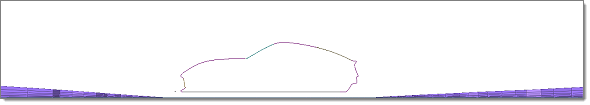
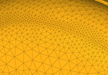
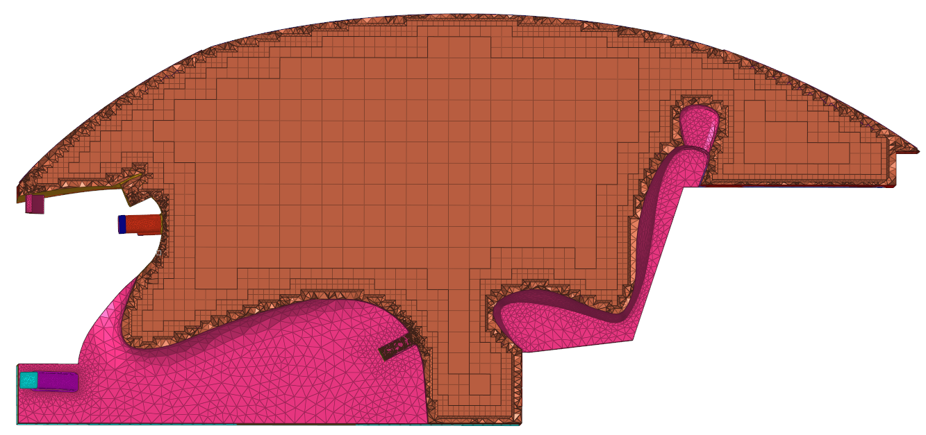
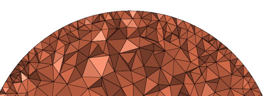
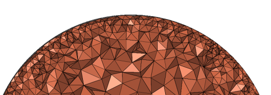
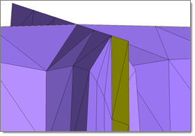
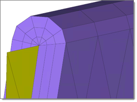
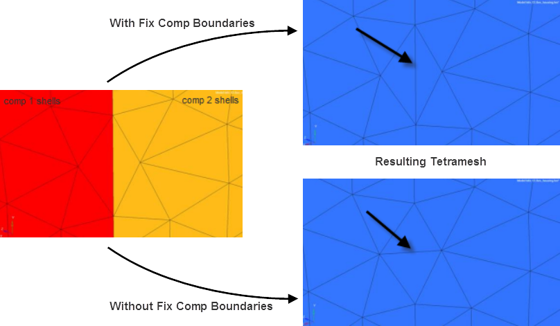


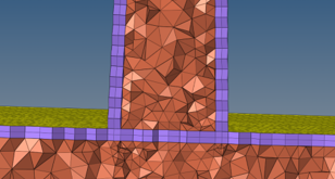 Figure 12. Bottom Solid as Parent