Batch Mesh
Typical workflow for creating a mesh using BatchMesher.
-
Define a mesh type.
A mesh type consists of a Criteria File and a Parameter File.
- Click the Configurations tab.
-
Click
 to add a
new configuration entry to the table.
to add a
new configuration entry to the table.
- In the Mesh Type field, enter a name.
- In the Criteria File and Parameter File fields, browse to select the criteria and parameter files that define the mesh type.
-
Choose the models to batch mesh.
-
Click
 to select
model files.
to select
model files.
-
Click
-
Click the Mesh Type field for each file and select a
relevant mesh type.
Tip: Quickly apply the same mesh type to all files above or below the current row by right-clicking and selecting Propagate Up or Propagate Down.
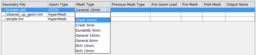
Figure 1.
Run Setup
Define settings for a batch mesh run and the jobs it contains in the Run Setup tab.
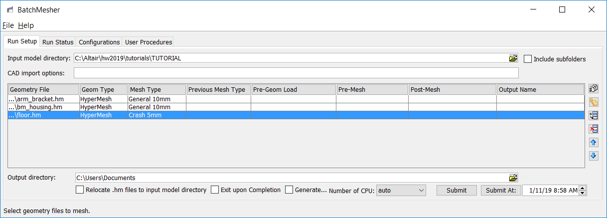
Figure 2.
For each geometry file in the table, a geometry type must be chosen in the Geom Type field. If you select files using the Select Model Files dialog, than the geometry type is automatically set based on the value in the dialog. Manually select a geometry type by left-clicking the Geom Type field. Select the Auto geometry type to automatically attempt to detect the model type during import.
Additionally, each file requires a mesh type to be chosen in the Mesh Type field. The available mesh types are defined in the Configurations tab. Select a mesh type by left-clicking the Mesh Type field. Clear the mesh type by selecting the empty row in the drop down list.
Job dependencies can be defined, where the output of one model is used as the input to another. This is useful, for example, when creating a common mid-surface geometry model that is then used as input to generate domain specific mesh models. Such dependencies can be defined using the Previous Mesh Type field. When a previous mesh type value is selected, BatchMesher will find another Geometry File with the same name and specified Mesh Type, and run that model first. The output from that model will then be used as the input for the dependent model. The order of the definitions does not matter, as BatchMesher will decide the appropriate order to run any dependent jobs. If there is no other Geometry File that has the specified Previous Mesh Type, BatchMesher will not execute the dependent model. Further, if there is an error in generating the previous model, BatchMesher will also not execute the dependent model.
Each entry can have user-defined procedures specified. The available procedures are defined in the User Procedures tab. To set a procedure, left click in the corresponding Pre-geom Load, Pre-Mesh or Post-Mesh field and select from the drop down list. To clear the procedure, select the empty row in the drop down list. Additional procedures for pre- and post-run can be specified in the User Procedures tab as well.
| Option | Description |
|---|---|
| Input model directory | Directory that contains the geometry/CAD files for batch
meshing. Note: You must select the directory containing the
CAD files and not the CAD files themselves.
The
Include subfolders option additionally lists CAD files in all
the subfolders of the selected directory. |
| CAD import options | CAD import strings can be provided to override default import
behaviors, for example "SplitComponentsBy=Parts". The provided
strings apply to all CAD import, regardless of format. Valid strings can be found in Supported CAD Readers. |
|
Launch the Select Model Files dialog to
selecting the individual files to be batch meshed.
Tip: Use the Shift and
Ctrl keys to select or
deselect multiple files from the list.
If the
Include subfolders checkbox is selected, matching files in
subdirectories are also listed. Once the selection is
complete, click Select to add the
selected files to the table.All files of the selected geometry type in the source directory are selected by default. The process can be repeated to add more files from different directories or to add the same files multiple times to generate different sizes/types of mesh. A new directory can also be specified and files can be selected from that location. In addition, double clicking in a row in the Geometry File column allows direct editing of the file name and path. |
|
|
Launch the Select Folder with Model Files dialog to select an entire directory to be batch meshed. Once a directory is selected, all of the files matching the specified geometry type are listed. If the Include subfolders checkbox is selected, matching files in subfolders are also listed. No selection of individual files needs to be made. After review, click Select to add the selected directory to the table. All files of the selected geometry type in the directory are included. The process can be repeated to add more directories or to add the same directories multiple times to generate different sizes/types of mesh. In addition, double clicking in a row in the Geometry File column allows direct editing of the directory name and path. |
|
| Add an empty row to the end of the table. | |
| Remove the selected row/rows from the table. | |
| Move the selected rows up in the table. | |
| Move the selected rows down in the table. | |
| Output directory | Directory where the BatchMesher
output files should be written. The results of the run are saved
in a subdirectory named
bm_<date>_<run>. For example, a
first run on Aug. 4, 2011 will be named
bm_110804_001. The next run on the same
day would be bm_110804_002. If no output directory is specified, the Input model directory will be used. |
| Relocate .hm files to input model directory | Move all .hm output files to the corresponding directory of the input model. |
| Generate quality report | Generate HTML quality reports for each model, and a summary report for each job. The reports can be loaded from the Run Status tab. |
| Exit upon completion | Close the BatchMesher GUI after all jobs are complete. |
| Number of CPU | Maximum number of simultaneous jobs that can be run. If set to "auto" for multi-CPU machines, this will default to the number of CPUs minus 1. |
| Submit | Start the BatchMesher run and automatically open the Run Status tab. A run can also be started at a later time using the Submit At option. |
| Submit At | Start the BatchMesher run at a specified time, and automatically open the Run Status tab. The job status is listed as "Waiting" until the time the run starts. |
Run Status
Once an BatchMesher run is initialized, the Run Status tab reports on the status of the run and its jobs.
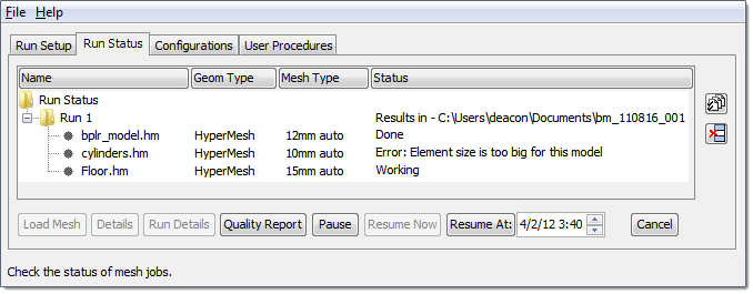
Figure 3.
- Working
- Batch meshing is currently being performed on this model.
- Pending
- This model is currently in the queue and has not started the BatchMesher process yet. Any models with the status can be canceled.
- Waiting
- The job will begin automatically at a user-specified date and time.
- Done
- The batch meshing process is complete, and results can be reviewed.
| Option | Description |
|---|---|
| Load a .log file from a previous run to be reviewed. | |
| Remove a run from the tree. Note: This only affects the user
interface; it does not delete any files.
|
|
| Load Mesh | Select a single job from the tree and use this button to
invoke interactive HyperMesh and
load the final batch meshed model. The corresponding criteria
file is also loaded in the QI panel so that the quality checks
represent the meshing requirements set in BatchMesher. Note: This can only be
performed on models that have a status of
Done.
|
| Details | Select a single job from the tree and use this button to
obtain more details on the status. The details include:
Click Refresh to manually
refresh the window with the latest details. Click
Auto Refresh to automatically update
the window with the latest details while the job is
running.
|
| Run Details | Select a run from the tree and use this button to obtain more
details on the status. The details include:
|
| Quality Report | Generate HTML quality reports
for each job, and a summary report for each run. Restriction: Only valid if the Generate quality report
checkbox was enabled on the Run Setup tab for the
run.
|
| Pause | Pause all pending jobs. This does not affect currently running jobs, which cannot be paused. |
| Resume Now | Resume all paused jobs. |
| Resume At | Resume all paused jobs at a future date and time. |
| Cancel | Cancel a single run. Runs that are Pending or Working can be canceled. |
Configurations
Define the available mesh types that can be used in BatchMesher jobs in the Configurations tab.
A mesh type is a name given to a set composed of one criteria file and one parameter file.
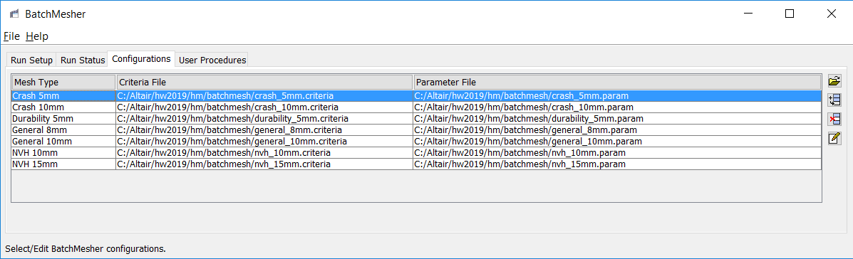
Figure 4.
- crash 5mm
- Sample template file for crash analysis with average element size of 5mm.
- crash 10mm
- Sample template file for crash analysis with average element size of 10mm.
- durability 5mm
- Sample template file for durability analysis with average element size of 5mm.
- general 8mm
- Sample template file for general use cases with average element size of 8mm.
- general 10mm
- Sample template file for general use cases with average element size of 10mm.
- NVH 10mm
- Sample template file for NVH analysis with average element size of 10mm.
- NVH 15mm
- Sample template file for NVH analysis with average element size of 15mm.
| Option | Description |
|---|---|
| Launch a dialog, from which you can select a criteria or parameter file, depending on the selected cell. In addition, double click a row in the Criteria File or Parameter File columns to edit the file name and path. | |
| Add an empty row to the end of the table. | |
| Remove the selected row/rows from the table. | |
| Launch the Criteria and Parameters Editors, from which you
can edit the criteria and parameters files in the selected
row. Note: It may not be possible to edit the default
parameter and criteria files provided in the installation
due to file permissions.
|
User Procedures
User procedures that can be specified in BatchMesher for jobs and runs in the User Procedures tab.
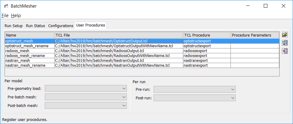
Figure 5.
- nastran_mesh
- Write out the resulting mesh in Nastran format.
- nastran_mesh_rename
- Write out the resulting mesh in Nastran format, but renames the output file.
- Pre-geometry load
- Select a user procedure to execute immediately after the job begins, before the input model is imported.
- Pre-batch mesh
- Select a user procedure to execute immediately after the input model is imported, before the batch mesh begins. Examples include extracting a midsurface or performing a surface offset.
- Post-batch mesh
- Select a user procedure to execute immediately after the batch mesh process is complete. Examples include creating solver specific cards, or exporting the mesh in a specific format.
- Pre-Run
- Select a user procedure to execute before the first model/job starts.
- Post-Run
- Select a user procedure to execute after the last model/job completes.
| Task | Description |
|---|---|
| Open a dialog, from which you can select a .tcl file. In addition, double-click a row in the Tcl File column to edit the file name and path. | |
| Add a empty row to the end of the table. | |
| Remove the selected row/rows from the table. |