Overview of the seam connector realization process and methods.
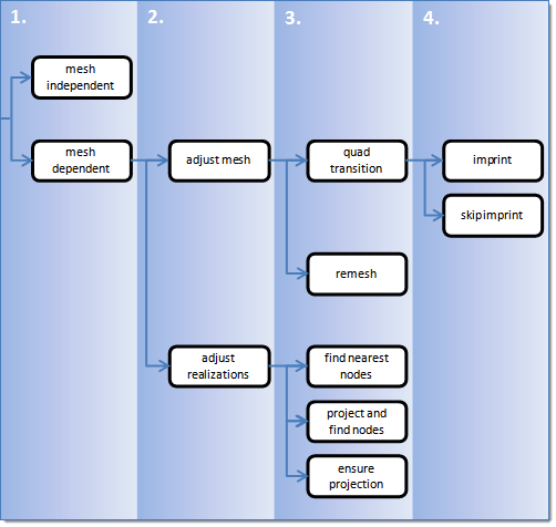
Seam Realization Process
Overview of the seam realization process.
Select the realization type.
mesh independent
Use for realizations which do not need a node connection and the
connection is primarily defined via a solver-specific card, such
as LLINKs for PAM-CRASH.
mesh dependent
Use for all other cases.
If mesh dependent is selected, you must decide
whether or not to adjust the mesh or the realization.
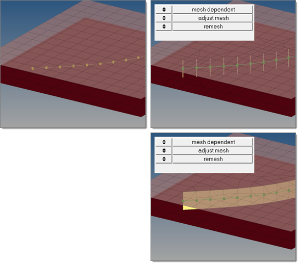
Adjust mesh
Projection is done in a perpendicular way, and the mesh has to
be adapted to the projection points.
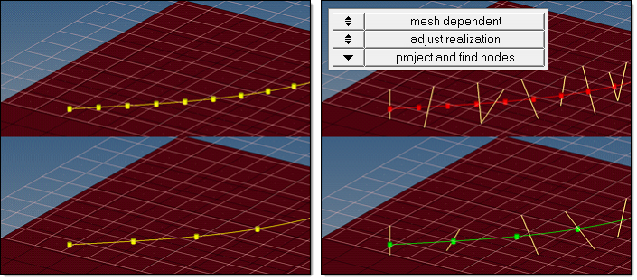
Adjust realization
The mesh will not be modified, at the expense of non-normal or
incomplete realizations. Many realization types are defined with
head elements attached to body elements. In the case of these
realization types, the head elements realize the connection
without modifying the mesh, and the body elements are created in
a normal direction.
Choose how the adjustments should take place.
Adjust mesh
Sub-options include: quad transition and remesh.
Adjust realizations
Sub-options include: find nearest nodes, project and find nodes,
and ensure projection.
Choose whether or not the imprint should be skipped for quad
transition.
Figure 1. Seam Realization Process
Seam Realization Methods
Overview of the different options for seam realization methods.
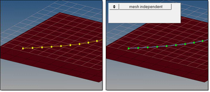
Mesh Independent
The mesh independent option is normally used for solver-specific realization types, then a
post script is performed during realization to define the solver specific connection. For
example, for the PAM-CRASH LLINK all necessary solver specific
cards are created along with the realization. Figure 2. Mesh Independent
The quad transition option creates perfectly shaped quad elements around the
projection line. The quad size is determined by the average mesh size. From one
projection point to the next, exactly one pair of elements is created. You can also
use this option to create seams from quad elements, and realize the connections to the
links through perfectly modeled t-edges.
In certain limits, the mesh automatically snaps to important features. This prevents
the creation of elements that are too small, and ensures that the geometry is not
modified too much.
The considered feature angle can be defined individually for each connector. Feature
edges below 10.0° will not be taken into account, whereas features above 25.0° and
free edges will always be taken into account.
By default, snapping is allowed by a distance of one third of the quad pattern
element size. In the case of a predefined quad pattern element size of 10.0, the outer
nodes can snap to features in a distance of 3.3. The algorithm also tries to snap all
three nodes of a quad pattern or none.
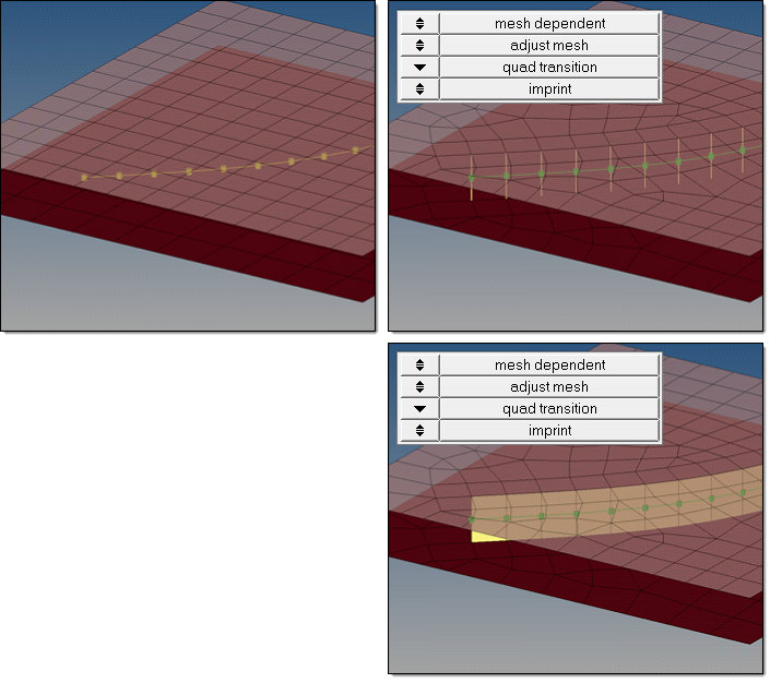
Imprint
When creating mesh-dependent realizations with quad transitions, the quad transition
meshes can overlap and disturb each other if more than one set of connectors is
created too close to each other. The imprint option reconciles such transitions with
each other and modifies the underlying mesh to match the results to create a final
result that is seamless and properly meshed.
To allow smaller imprint conflicts to be automatically resolved when connectors are
realized, the resolve conflicting imprints checkbox is enabled
by default. Overlapping elements are released, and a normal remesh of that area is
performed as long as the overlapping area is smaller than half the regular quad
transition element size. Larger conflicts may require a manual imprint.
The size of the imprint can be determined using the pitch size (use pitch size to
imprint) or using the average size of the underlying mesh (use avg. mesh size to
imprint). If you want to define a specific imprint size, select size to
imprint. Figure 3. Imprint
The quad transition option creates perfectly shaped quad elements around the
projection line. The quad size is determined by the average mesh size. From one
projection point to the next, exactly one pair of elements is created. You can also
use this option to create seams from quad elements, and realize the connections to the
links through perfectly modeled t-edges.
In certain limits, the mesh automatically snaps to important features to prevent the
creation of elements that are too small, and to ensure that the geometry is not
modified too much.
The considered feature angle can be defined individually for each connector. Feature
edges below 10.0° are not taken into account, whereas features above 25.0° and free
edges are always taken into account.
By default, snapping is allowed by a distance of one third of the quad pattern
element size. In the case of a predefined quad pattern element size of 10.0, the outer
nodes can snap to features in a distance of 3.3. The algorithm also tries to snap all
three nodes of a quad pattern or none.
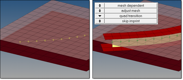
Skip Imprint
The skip imprint option prevents the last step of quad transition from being
performed. The component ^conn_imprint is created instead, which contains the element
pattern. These elements can be modified and manually imprinted later using the
Connector Imprint panel.
Skip imprint enables you to realize such mesh-dependent realizations, even in very
complex areas of the model where the automatic imprint fails because of issues such as
conflicting seams.
The size of the imprint can be determined using the pitch size (use pitch size to
imprint) or using the average size of the underlying mesh (use avg. mesh size to
imprint). If you want to define a specific imprint size, select size to imprint. Figure 4. Skip Imprint
Mesh Dependent – Adjust Mesh – Remesh
The remesh option uses snap and split capabilities to connect 1D welds to the links in the
position of the projection points. In the case of a quad realization, remesh looks for a
correct t-edge. Figure 5. Remesh
The find nearest node option searches for the nearest nodes within the given tolerance,
making it possible to connect t-joints and similar areas. This option is very useful in
situations where the connectors are not positioned perfectly. These realizations are allowed
to be non-normal. Find nearest nodes does not do any projection.
Note: If the connector
points are close to each other and two of these points find the same closest nodes the
connector fails.
Figure 6. Find Nearest Nodes
Mesh Dependent – Adjust Realization – Project and Find Nodes
The project and find nodes option produces the same exact result as find nearest node
because a non-normal projection for seams is always allowed. Principally, project and find
nodes requires a valid projection onto the link entities in the first step. In the second
step, the nodes closest to the projection points will be used for the connection. If the
projection (connector tolerance) is not possible, the realization fails.
Note: The
realization fails when the connector points are close to each other, and two of these
points find the same nodes.
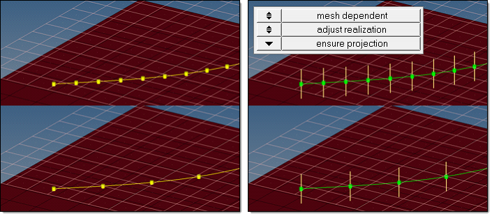
When using the ensure projection option, the minimum condition for the realization is a
possible normal projection. The realization will be performed in the direction from one
projection point to the next. If the projection point is coincident with a shell node they
will be equivalenced.
Ensure projection can lead to incompletely defined connections from a solver perspective
unless the connector positions are not aligned to the mesh. The advantage of this projection
method is the exact determination of the projection points.
The ensure projection option is comparable to the older use shell node option, which is no
longer available. Figure 8. Ensure Projection
Stitch Connector
The stitch connector is unique among connectors in that there is no inherent realization.
It is designed to tie the mesh between its links.
Table 1. Stitch Connector Options
Option
Description
Select a Parent Link
Takes the lead link information from the selected item. In most situations,
this can be left blank and it will be determined internally by the shape of the
weld. For example, a T joint or a Lap joint.
After Stitch
Realization options for how the mesh is tied together.
Keep Node IDs
Describes how to maintain the best possible numbering of the end nodes when
tying the two plates together.
Imprint Project Options
Specifies the shortest projection or tangency to keep the shape of the plate
if there is a shorter projection.