Extract Forces
Extract grid point force data, including forces and moments, for a user-defined element set.
Extracting FBD forces is useful for doing breakout modeling within a sub-modeling scheme.
Results can be output to load collectors for graphical review, a text summary table, and/or a formatted Comma-Separated Values (.csv) file which can be loaded into traditional spreadsheet software packages.
-
From the menu bar, click Post > Free Body > Force.
The FBD Forces tab opens.
-
In the .op2/.odb file field, specify the full path and filename of the results
file containing the forces output for the current model.
Once you have selected an results file, loadstep names and IDs with grid point force output are saved to the database for use with all FBD utilities. The loadstep name and ID information is retained within the HyperMesh database once saved.
If a new results file is required, or if the original results file changes, you must load the new results file into the database, overwriting the previously selected.
-
In the Loadsteps section, select which loadstep(s) to extract grid point force
information.
Loadsteps with grid point force results from the currently selected results file are displayed for selection only. Multiple loadsteps can be selected via Ctrl-click or Shift-click functionality. Filter buttons allow for additional selection control as shown including a name filter that uses standard filtering syntax. The loadstep list can be switched between ID and Name (ID).
The ID option lists the loadsteps in the format SUBCASE ID. The Name (ID) option lists the loadstep in the format NAME – ITERATION (ID).
-
Select entities.
-
Use the Element Set selector to define the elements that make up the
free body and contain the nodes at which GPFORCE data will be
extracted.
The Set Browser tool can be used to create the necessary element sets.
-
Use the Result System selector to define the coordinate system into
which the grid point force and moment result vectors are transformed and
output.
If a results system is not specified, the HyperMesh "base" system is used by default.
The FBD Forces utility extracts grid point force and moment results from an results file in the output coordinate system in which the solver output these results. HyperMesh assumes that the output coordinate system assigned to each node in the HyperMesh database matches that used to run the analysis and generate the results file. Output coordinate systems are defined in HyperMesh by accessing the Systems panel. On the assign subpanel, select the required nodes and a coordinate system, and click Set Analysis. In OptiStruct and Nastran this operation sets the CD field on the GRID card(s).
If the output coordinate systems for each node in the HyperMesh database do not match those used to run the analysis, the extracted values will be incorrect. This could occur when modifying a nodal output system within HyperMesh without rerunning the analysis and, or when loading a results file that does not match the currently loaded model. In addition, results coming from, or output to, cylindrical or spherical result coordinate systems should be inspected for validity near the origin and along principal axes.
-
Use the Summation Node selector to define the node about which the
GPFORCE data is summed for the selected element set.
This is useful for verifying free body behavior through zero-sum values for all force and moment components about any node. It is also useful for calculating the result of applied or reaction forces about any node. If a node is not selected, the HyperMesh origin (0,0,0) is used by default.
-
To automatically display the entire model in transparency mode while
highlighting the currently selected element set, result system and
summation node, select the Show Model
checkbox.
This allows you to verify which element sets is currently selected.
-
Use the Element Set selector to define the elements that make up the
free body and contain the nodes at which GPFORCE data will be
extracted.
-
Define output options.
-
For FBD type, select the type of grid point force and moment data to
extract and utilize for FBD calculations for each node in the selected
element set.
- Choose All Loads to extract and utilize all element contribution, applied, SPC, and supported MPC grid point data for FBD calculations on the nodes in the selected element set.
- Choose Applied Loads Only to extract and utilize only the applied loads grid point data for FBD calculations on the nodes in the selected element set.
- Choose Reaction Loads Only to extract and utilize only SPC and supported MPC grid point data for FBD calculations on nodes in the selected set.
-
In the Zero Tolerance field, enter the cut-off point below which a
result quantity is considered zero.
All calculations are performed with floating point precision and the zero tolerance value is only used to control the output of results to the various formats. This option helps to prevent relatively small values from being output to the result formats. To maintain floating-point precision the default is set to 1.0e-6; modify the value as desired.
-
To extract the specified grid point data and display it in organized
load collectors for visualization in the model window, select the
Create Load Collectors checkbox.
Multiple load collectors are created — one for each force and moment component — for each selected loadstep of the current element set. The load collector name format is "FBDF_E(#)_S(#)_(compID)". For example FBDF_E(1)_S(1)_Fx would be created for element set 1, loadstep 1, and component Fx. In addition a load collector with the Nastran/OptiStruct LOAD card is also created, referencing the component force and moment load collectors. This load collector is named "FBDF_E(#)_S(#)_C" and can be referenced in the loadstep panel as the LOAD entry for the various loadstep definitions.Tip: To choose a color for all created load collectors, click the Color button. This color can be modified later using either the interface or the FBD Results Manager utility.
The FBD Results Manager can be used to review the load collectors generated from FBD Forces utility. When you save the database, all FBD Forces load collectors are saved to the database. This allows FBD information to be reviewed and utilized in the future without having to rerun the tool. Renumbering element or node sets after running the tool invalidates the link between the load collector names and the associated sets; therefore it is important to avoid renumbering any element or node sets for which FBD result must be retained as load collectors in HyperMesh.
-
To output the results to a popup window for instant review, select the
Show summary table checkbox.
The table contains information about the loadsteps, element set(s), and detailed data from the grid point extraction at each node.
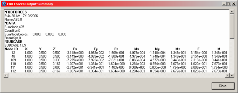
Figure 1. -
To create a .csv file that contains the same
information as the summary table, but in a comma-separated file, select
the Create .csv file checkbox and select a new
file or an existing file.
If the data you are extracting already exists in the file, based on element set, loadstep IDs, the existing block will be overwritten with the new data. If it does not exist, it will be appended to the end of the file.
You are asked if you wish to replace the existing file. However, selecting yes will not overwrite the file, it will append/replace the data as described above.
-
For FBD type, select the type of grid point force and moment data to
extract and utilize for FBD calculations for each node in the selected
element set.
- Click Accept.