Empirical COST-Walfisch-Ikegami Model
The empirical COST-Walfisch-Ikegami model considers only vertical plane propagation for faster prediction. Accuracy is reduced but is acceptable in specific scenarios described.
The so-called empirical models (for example, the model according to Walfisch/Ikegami) consider only the propagation in a vertical plane which contains the transmitter and receiver. For the field strength prediction, significant parameters have to be extracted from this vertical section (for example, average building height).
Equations containing these parameters have to be optimized and fitted to numerous measurements to get a prediction model which is applicable in different propagation environments. The main advantage of empirical models is their short computation time.
However, their prediction accuracy is limited because only a small number of parameters is taken into account and the influence of the distance from the transmitter is over-emphasized. Additionally, wave guiding effects in streets cannot be considered with an empirical approach.
- height of the transmitter
- height of the receiver
-
mean value of building heights
- mean value of widths of road w
- mean value of building separation b
- road orientation with respect to the direct radio path
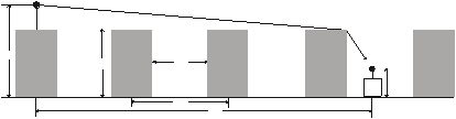
Figure 1. Typical propagation situation in urban areas and the definition of the parameters used in the COST-Walfisch-Ikegami model.
However, this model is still statistical and not deterministic because only characteristic values are taken into account for the prediction. The model distinguishes between line-of-sight (LOS) and non-line-of-sight (NLOS) situations. In the LOS case – between the base station and mobile antenna within a street canyon – a simple propagation loss formula different from free space loss is applied. The calibration of this formula is done by measurements performed in European cities.
LOS case:
where the first constant is determined in such a way that is composed of the terms, free space loss , multiple screen diffraction loss , and rooftop-to-street diffraction loss :
NLOS case:
The free space loss is given by:
The term describes the coupling of the wave propagation along a multiple screen path into the street where the mobile station is located. The determination of is mainly based on Ikegami’s model. It takes into account the width of the street and its orientation. COST 231, however, has applied another street-orientation function to improve on the Ikegami model:
The orientation loss is an empirical correction factor gained from measurements:
A scalar electromagnetic formulation of multi-screen diffraction results in an integral for which Walfisch and Bertoni published an approximate solution for the case of base station antennas located above rooftops. This model is extended by COST 231 for base station antenna heights below the rooftop levels using an empirical function based on measurements. The heights of buildings and their spatial separations along the direct radio path are modeled by absorbing screens for the determination of :
where:
The COST-Walfisch-Ikegami model is valid in the following ranges:
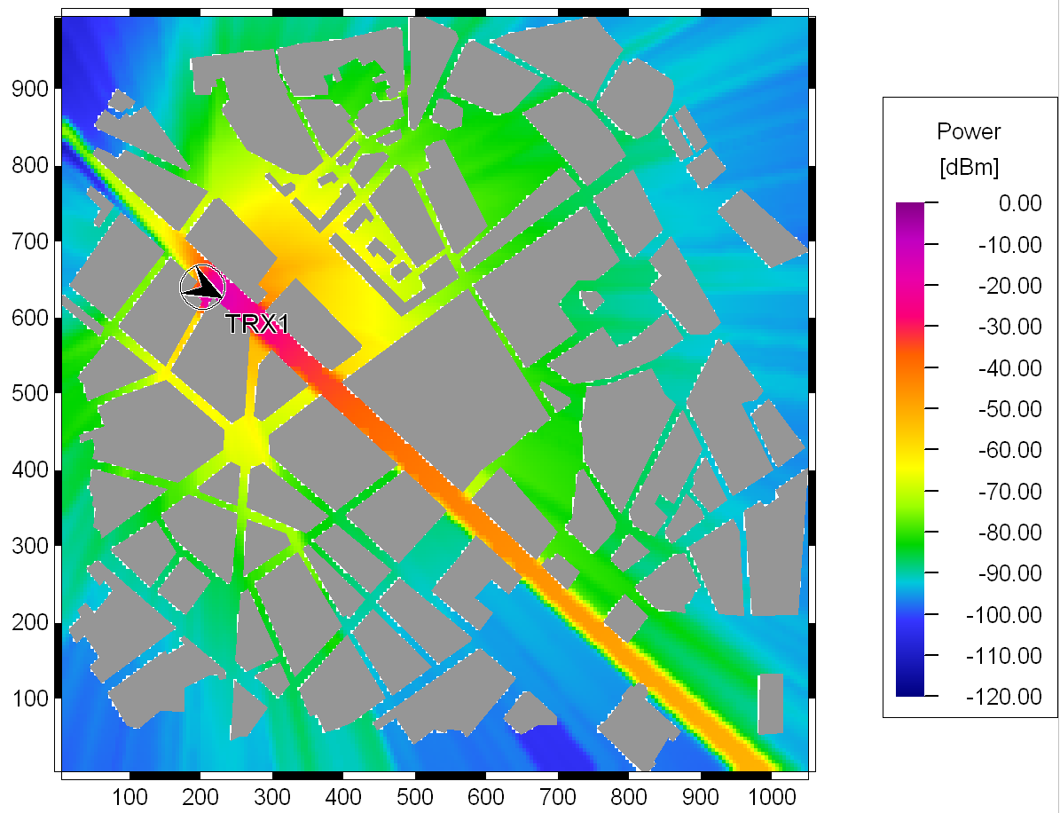
Figure 2. Prediction with the COST-Walfisch-Ikegami model in an urban area.
The model has also been accepted by the ITU-R and is included in report 567-4. The estimation of path loss agrees well with measurements for base station antenna heights above rooftop levels. The mean error is in the range of 3 dB, and the standard deviation is 4-8 dB. However, the prediction error becomes larger for close to compared to situations where . Furthermore, the performance of the model is poor for . The parameters b, w and are not considered in a physically meaningful way for micro cells. Therefore the prediction error for micro cells may be quite large. The model does not consider multipath propagation. Therefore wave guiding effects in street canyons are not taken into account. But in situations where the propagation over the rooftops is dominant, the model produces good results.
Because of the calibration with measurements from European cities no parameters have to be adjusted when using this model. However, with this empirical approach, it is not possible to predict the wideband properties of the mobile radio channel such as the delay spread or impulse response. Further information is available in Damosso1.