Example
This section presents an example for the better understanding of the MIMO feature in WinProp.
The figure shows an office scenario with two antennas (distributed MIMO system). Both antennas use the same carrier - otherwise there would be no co-channel interference in the scenario.
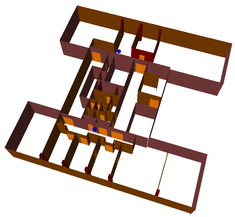
Figure 1. Office scenario with two antennas (DAS or MIMO 2x2).
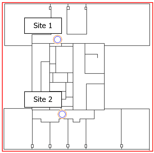
Figure 2. Office scenario (3D) with two antennas (DAS or MIMO 2x2).
The main parameters of the network are shown in the following table:
| Parameter | Value |
|---|---|
| Frequency | 2630 MHz |
| System bandwidth | 20 MHz |
| Transmit power | 5 dBm Output power of PA |
| Antenna height | 2.5 m |
| Min. required SNIR (depending on MCS) | Between –5.4 and 17.2 dB |
| Air interface | LTE |
- Configuration 1: Both sites are conventional antennas forming a DAS (Signal Group A).
- Configuration 2: Both sites are MIMO antennas (Signal Group A) and transmit individual MIMO streams (site 1 MIMO stream 1 and site 2 MIMO stream 2).
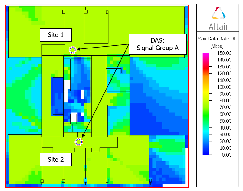
Figure 3. Maximum data rate (DL) for DAS network (configuration 1).
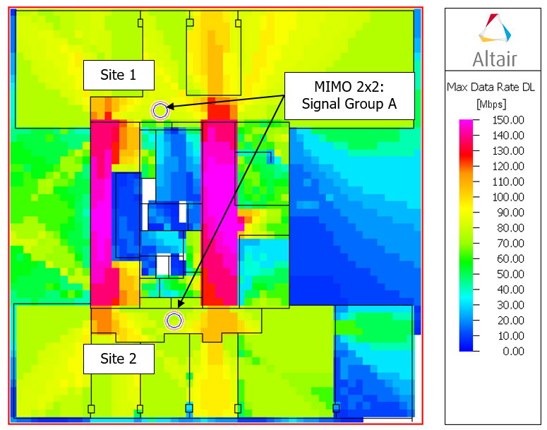
Figure 4. Maximum data rate (DL) for DAS network (configuration 2).
In configuration 1 both antennas operate on the same carrier and form a distributed antenna system. Because of that the signals from both antennas are superposed constructively and improve the SNIR situation. Nevertheless the maximum data rate is limited to 75 Mbit/s as only one data stream can be transmitted.
Configuration 2 shows where again both antennas operate on the same carrier, but this time sites 1 and 2 form a 2x2 MIMO system. Here MIMO stream 1 is transmitted from site1 and MIMO stream 2 is transmitted from site 2 in spatial multiplex. Accordingly higher data rates can be achieved for a large part of the office building (assuming here ideal separation of the different MIMO streams). Generally the performance depends also on the interference between the MIMO streams.
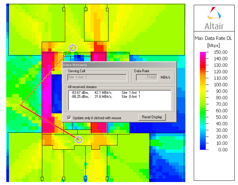
Figure 5. Maximum data rate (DL) for MIMO 2x2 network with visualised MIMO streams.
The above figure shows the active MIMO streams 1 and 2 contributing to the maximum data rate for a specific pixel (red shows the best received stream with the maximum data rate, in dark red color the other MIMO streams are given).