Graphical Input of a New 2D Antenna Pattern
After a new pattern is created (with or without bitmap), you must first decide if it is a vertical or a horizontal pattern. This is asked after clicking with the mouse button anywhere in the display.
Figure 1. The Select type of antenna pattern dialog.
You can define the gains in different directions by clicking with the right mouse button on the screen. This action inserts points with defined angle / gain relation (see Figure 2 and Figure 3).
If the mouse cursor is located on a point already defined and if the right mouse button is clicked, a context menu appears to ask if the already defined value should be deleted (as it is not possible to define to different gains for the same angle).
With the left mouse button points already defined can be moved (while the button is pressed). The point currently selected is automatically changed to the current mouse position if the limitation of the angle in the settings is not enabled. If it is enabled, only the selected point is modified.

In the Edit menu an UNDO function is available. If a point is drawn incorrectly, you have the option to remove it from the list via the UNDO command.
Especially if patterns are generated by the user (either drawn manually or entered numerically), many points are not defined. To increase the accuracy (especially for 2x2D to 3D interpolation), you can interpolate the pattern. The angle increment after the interpolation between the pixels can be defined in a dialog.
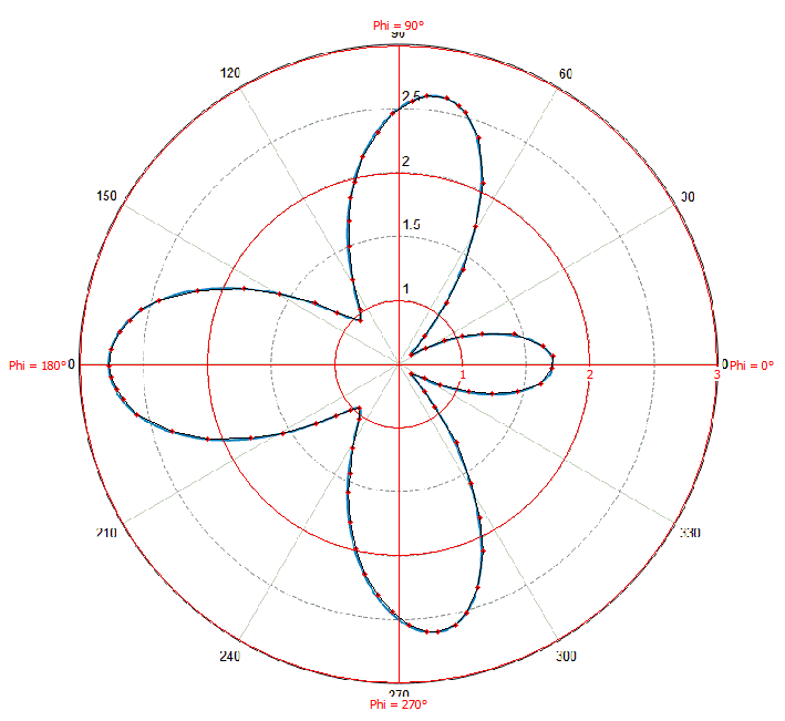
Figure 2. Inserting sample points to describe the antenna pattern (display with bitmap).
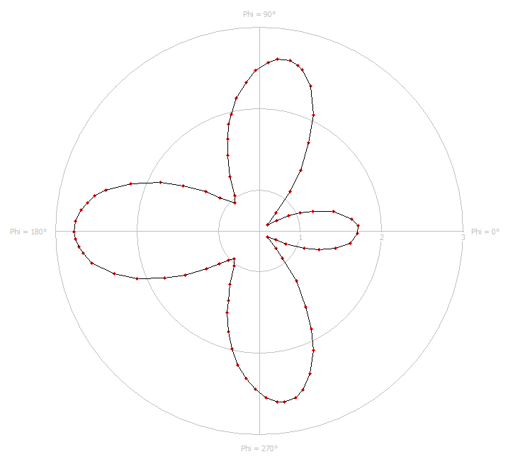
Figure 3. Inserting sample points to describe the antenna pattern (display without bitmap).