Generation of Antenna Patterns for 5G
Import antenna patterns and combine the patterns to use in 5G network planning.
Beamforming in 5G
In 5G wireless communication, base-station antennas may be antenna arrays that can form beams that point at specific mobile stations. Depending on the beamforming technology, these antenna arrays may have a limited set of directions in which a beam can point. Figure 1 shows an example of two possible beams out of a finite set.
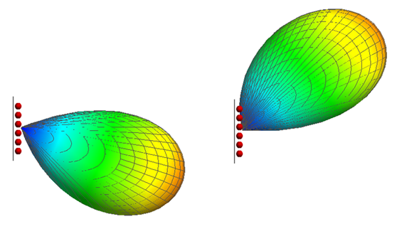
Figure 1. Examples of beam patterns achieved with phased arrays at a base station (top view).
- Strategy one is to avoid the problem of specifying which beams are active
and to work instead with the envelope pattern of all possible beams. This
assumes that the base station’s beam switching logic is working well, so any
mobile station is served with the best beam for its location. An example of
an envelope pattern is shown in Figure 2.
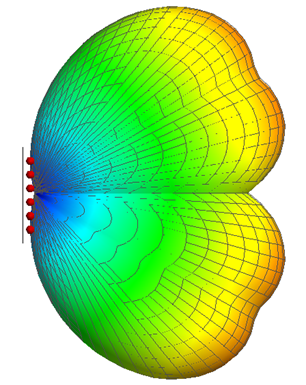
Figure 2. Envelope antenna pattern for a set of four beams (usually the set would be larger). - Strategy two is to specify the individual beams. This is usually combined
with a Monte-Carlo analysis in which the positions of individual mobile
stations are varied.The specification of envelope patterns and individual beams is accommodated in AMan by two features:
- Convert to beams and envelope patterns
is useful when the antenna patterns of the individual beams are available in individual antenna-pattern files, for example, from a simulation or a measurement. The Convert to envelope and individual beam patterns dialog enables you to select the files that contain the patterns of the control beams and data beams. The contents of the files are combined into larger files with the appropriate formats.
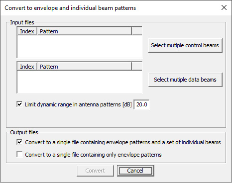
Figure 3. The Convert to envelope and individual beam patterns dialog. - Generate beams and envelope patterns
is useful when the patterns of individual beams are not readily available. The Generate envelope and individual beam patterns dialog requires input data as shown in Figure 4.
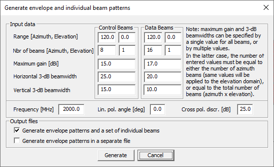
Figure 4. The Generate envelope and individual beam patterns dialog.User-defined beams can be specified using the following options (applicable to both Control Beams and Data Beams):- In the fields for gain and beamwidth, specify a
single value per field which will be applied to all
beams.
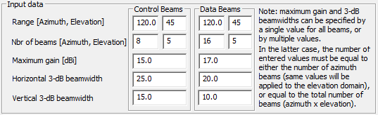
Figure 5. Example 1: for the Control Beams, a single value is applied to both the azimuth and elevation beams (similar for Data Beams). - Specify multiple values in the azimuth domain.Note:
- The number of values for gain and horizontal beamwidth must equal the number of azimuth beams.
- The same values are applied to the elevation domain.
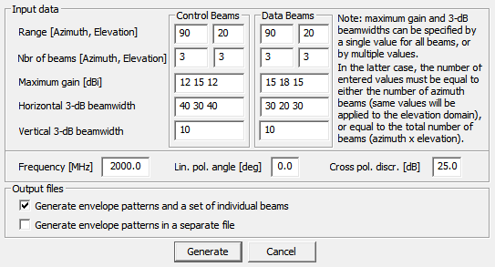
Figure 6. Example 2: for the Control Beams and Data Beams, three values are entered for the gains and three for the horizontal beamwidths. These govern the horizontal distributions. - Specify multiple values in the azimuth and elevation domain.Note:
- The number of values must equal the total number of beams (elevation*azimuth).
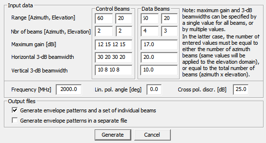
Figure 7. Example 3: for the Control Beams, four values are entered for the four beams (two beams in azimuth and two in elevation).
- In the fields for gain and beamwidth, specify a
single value per field which will be applied to all
beams.
In both cases, .ffe files with 5G-specific antenna pattern information are written to disk and can be used by ProMan.
- Convert to beams and envelope patterns