Add Point Vents
Add point vents to enable gases to escape from around the part and through the exterior of the mold.
You must create or designate a mold for your model before
adding vents.
-
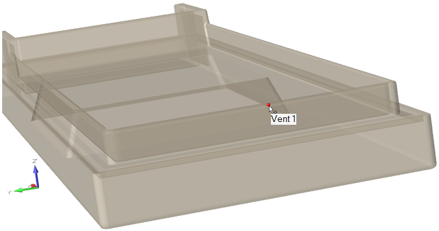
Click the Point Vent icon.

-
Click a surface on the part to place a point vent.
-
Use the microdialog options to define the parameters of the point vent.
Microdialog option Description Note Move Line Vent 
Click the Move tool to change the location of the
vent.Alternatively, enter the X, Y, and Z coordinates for the vent. Vent Shape 
Circular: Circular vents release gasses through the exterior of the mold.
Square: Square vents enable air to escape from around the part in the mold.Select a shape for the vent. For circular, enter the radius of the vent. For square, enter the X, Y and Z dimensions of the vent. Porosity 
The porosity value is the filtering capacity of the vent to syphon gases away from the part. Enter a value between 0 and 1, where 0 means no gases can escape and 1 means gases can fully escape. Variable Pressure 
Variable pressure defines a time-dependent venting system, including vacuum conditions, that can be applied to circular vents to syphon gases away from the part. Select the check box if your model includes a pressure system. To define the pressure properties, click the variable pressure button and enter the pressure over
time in the dialog: 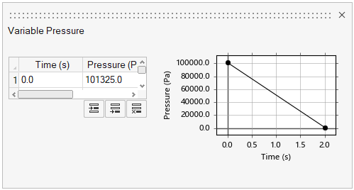
Tip: You can review, modify and work with vents in the Vents table. Click
the List Vents icon:

The table shows the current coordinates and radius or dimensions for each vent. Column 1 numbers the vents in the order that you added them.
The table shows the current coordinates and radius or dimensions for each vent. Column 1 numbers the vents in the order that you added them.