Tutorial: Inspire Friction Stir Welding Model Setup
Set up and complete a friction stir welding analysis and post-process the data.
In this tutorial you will learn about the Inspire Friction Stir Welding interface and how to:
- Import die geometry
- Set up an analysis for a simple butt joint.
- Launch HyperXtrude solver to run friction stir welding analysis
- Post process the results
Open the Tutorial Model
Data files are available in the tutorial_models folder in the installation directory in Program Files\Altair\2021\InspireExtrude2021.1\tutorial_models\fsw\tutorial-1\.
-
1. Open the butt-joint.x_t tutorial model file.
Select Materials
-
From the Friction Stir Welding ribbon, click the
Materials tool.

-
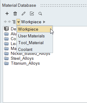
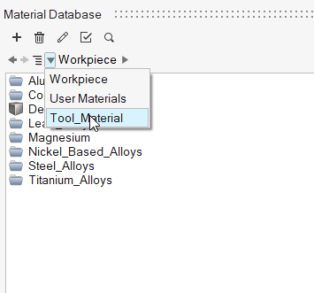
In the Material Database dialog, to the right of
 , click the triangle and select Workpiece.
-
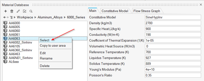
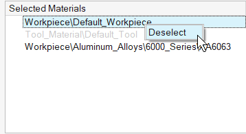
3. Select the workpiece material AA6063. Right-click on
the material and select Select.
-
Right-click on the Default_Workpiece material in the
selected materials and click Deselect.
-
To the right of , click the triangle and select Tool_Material.
-
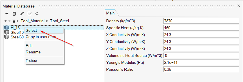
Select the tool material H_13. Right-click on the
material and select Select.
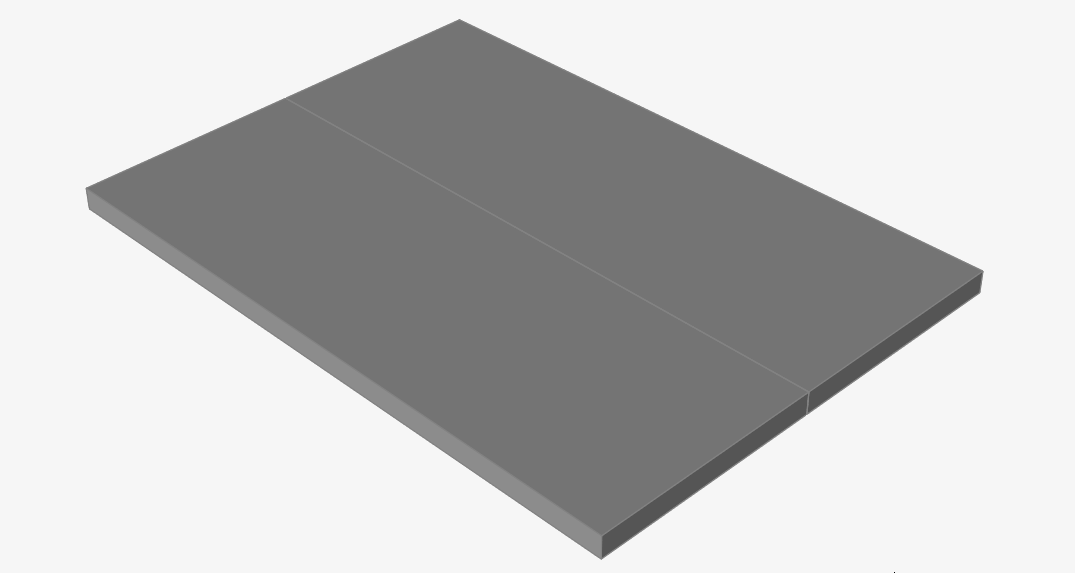
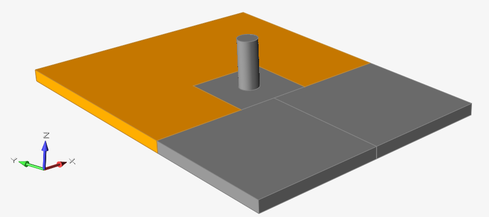
Identify the Plates
-
Click the Plates icon.

-
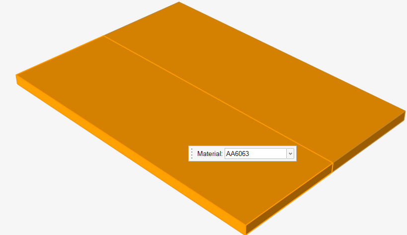
Select both left and right plates in the model,
and select the material AA6063 in the microdialog.
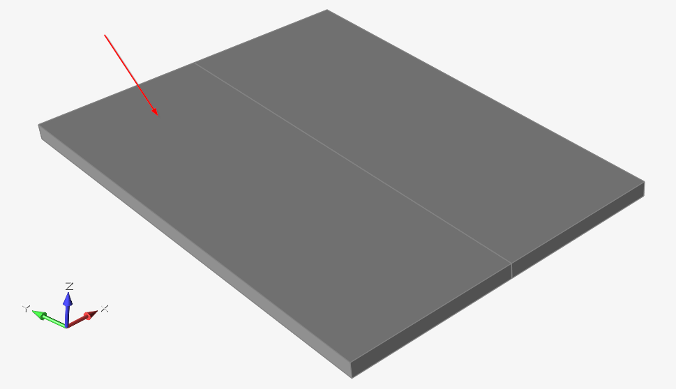
Orient the Model
-
Click the Orient icon.

-
Select the top surface that will be pierced by the pin.
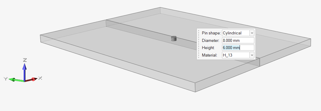
Create the Pin
-
Click the Pin icon.

-
Modify the pin geometry and specify the pin material with the
microdialog.
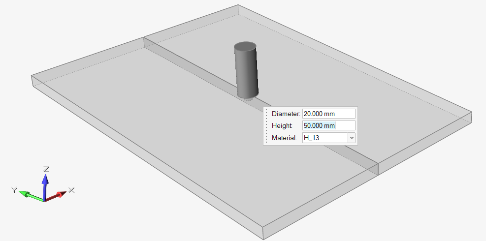
Create the Shoulder
-
Click the Shoulder icon.

-
Modify the shoulder geometry and specify the pin material with the
microdialog.
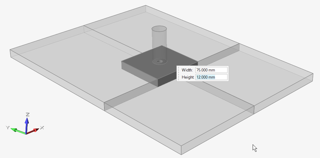
Create HAZ
-
Click the HAZ icon.

-
Enter the HAZ dimensions in the microdialog.
Specify Process Parameters and Simulate
-
Click the Submit Job icon.

-
Enter the analysis parameters.
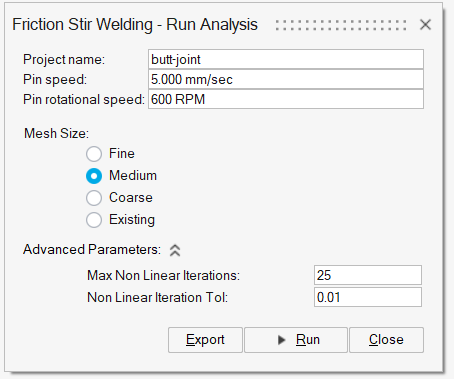
Note: To see Advanced Parameters options, you must have enabled it in Preferences.
View Simulation Results
-
Select the Temperature result type.
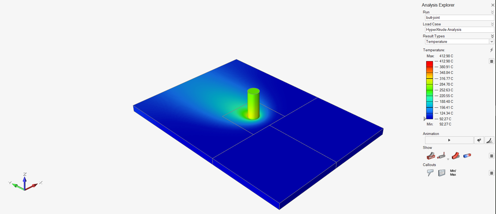
-
Click the Play button in the
Animation ribbon.