Run Optimization on a Part
Use the Run Part Optimization tool to define and run a topology, topography, or gauge optimization on a motion part.
Prerequisite: Before optimizing a part, run a motion
analysis. You will also need to designate at least one part as a design space using the
context menu.
-
Click Run Optimization
 on the Optimize Part icon.

-
Select a design space to optimize. The Run Part
Optimization window appears.
Note: Known Issues and Workarounds
- Joints connected directly to a design space may not be restored after exiting the Optimize Part tool. The workaround is to utilize a non-design space partition when making connections (joints, motors, or actuators) to a design space, and to put the partitions with the design space into a single rigid group.
- Significant performance issues may be encountered when using Optimize Part on motion models with lots of motion contact force vectors. The workaround is to change your modeling approach to either reduce the number of motion contacts or to altogether avoid the use of motion contacts on the design space (or any of its non-design space partitions).
Exporting an FEM File
-
Click Run Optimization on the Optimize
Part
icon. The Run
Optimization window appears.
- Click the Export button on the Run Optimization window and select a unit system for export.
- Choose a directory and a name for your file, then click Save.
- When the export is complete, double-click the name of the run to open the directory where the FEM file is located.
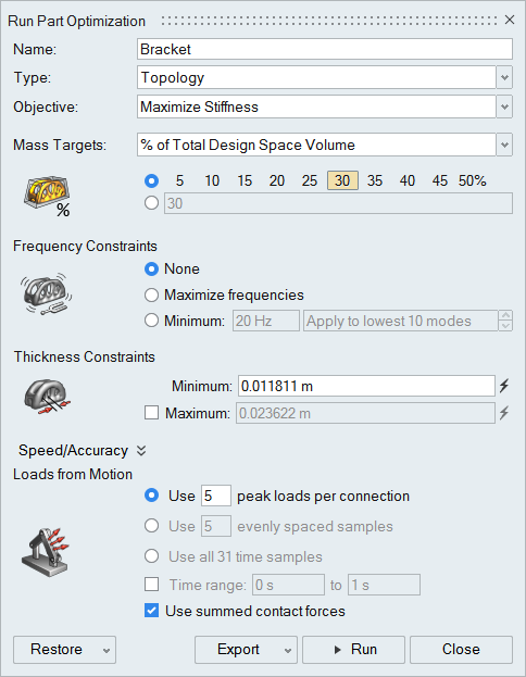
Loads from Motion
When you optimize a part using a motion run, the part is loaded from the results of the motion simulation. You can choose to select which points in time are optimized by extracting the peak loads, evenly spaced time samples, all time samples, or range of times.
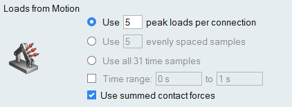
- Use # peak loads per connection: This option will extract time samples where peak loads occurred during the previously run motion analysis. This is the default option.
- Use # evenly spaced samples: This option will extract evenly spaced time samples from the previously run motion analysis. This is useful for reducing the number of runs.
- Use all # time samples: This option will extract loads from all time samples from the previously run motion analysis. This is useful for capturing loads from an entire motion cycle.
- Time range # to #: Select the checkbox to define a time window to limit the number of samples. This can be applied to any of the three options above.
- Use summed contact forces: This option will use a Summed at Contact Region representation of the contact forces instead of the individual contact forces themselves.