Add/Edit Joints
Add or edit joints, and detect features where joints can be placed.
- Use the guide bar to find features where joints can be placed, and to select what type of joint to create.
- Use the find options on the guide bar to change the search criteria for locations where joints can be placed.
- Use the microdialog to change a joint's type and how it is constrained.
- Use the Property Editor to change a joint's behavior (rigid vs. flexible), connection stiffness, part order, friction, and other advanced properties.
- Suppress/Unsuppress a joint to understand its effect on your model. On the joint, right-click and select Suppress. From the Model Browser or Table, right-click and select Unsuppress.
Create a Joint
Detect features where a joint can be created, select what type of joint to create, then click Connect All.
Tip: Hold Ctrl as you select the Joints tool to
bypass the autfofind feature.
-
On the Structures ribbon, select the Joints tool.

Joint detection begins automatically, but can be stopped by clicking the Find button. Detected features are displayed in red. -
Filter the results.
- Select All on the guide bar to intelligently find features where a joint can be placed.
- Select a different option to filter for a specific type of feature, such as aligned holes or cylindrical pairs.
- Use the
 menu to refine your search criteria.
-
Click the Apply
 button on the guide bar to automatically create joints in all of the selected
(red) features, or left-click selected (red) features to create joints
individually.
button on the guide bar to automatically create joints in all of the selected
(red) features, or left-click selected (red) features to create joints
individually.
-
Select a joint to edit it.
- Use the microdialog to change the joint's type and how it is
constrained.
- Hold the Ctrl key to tour joints that have been created while in editing mode. Note that you must select a joint first before using the Ctrl key.
- Use the microdialog to change the joint's type and how it is
constrained.
Tip:
- Joint types include grounded pin and grounded sliding pin. Grounded joints appear under Load Cases in the Model Browser, instead of under Connectors.
- A common reason why joints aren't found is because the geometry isn't touching. Turn off the Auto search distance in the Find Options and enter a search distance manually.
- If the Find operation does not detect all of the features you expected to see, try increasing the Search Tolerance in the Find Options.
- If you already have a joint defined, but don't see the joint types you expected in the Joints microdialog or table, try adjusting the Search Distance in the Joints table.
- Some connection tools automatically detect relevant features when the tool is opened. You can disable this behavior in the Preferences under .
- To connect a part to ground, you may want to use the Supports tool.
- The name of a joint in the Model Browser also displays its type in parentheses, or its state if free or locked; only the name is editable.
- Suppress/Unsuppress a joint to understand its effect on your model. On the joint, right-click and select Suppress. From the Model Browser or Table, right-click and select Unsuppress.
Find Options
Click the menu on
the guide bar to filter the results of the find operation.
- Find Larger/Smaller/Similar
- Find holes that are smaller, larger, or similar (±5%) in size to selected holes.
- Options
- Click to specify options for the find operation.
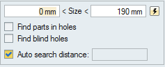
- Size
- Specify a minimum and maximum size range for the hole diameter. This option applies to
Aligned Holes and Single Holes. Click the
 icon to
reset the default value.
icon to
reset the default value. - Find Parts in Holes
- If enabled, the Joints tool automatically finds existing geometry in holes, hides it, and deactivates it so that it is not included in analysis or optimization calculations. Deselect Find Parts in Holes to disable this behavior, in which case you will need to delete the existing geometry manually.
- Find Blind Holes
- Enable to automatically detect blind holes during the find operation.
- Auto Search Distance
- This is a global search threshold that uses default tolerances to find locations where joints can be created. When the checkbox is enabled, it is calculated automatically. To change the search distance, deselect the checkbox and enter a value in the text box. Any joints with a minimum gap less than the entered search distance will be found. (The minimum gap is the exact minimum distance between the two parts.)
Microdialog Options
Use the options in the microdialog to change the joint type and how it is constrained.
Figure 1. Joints Microdialog
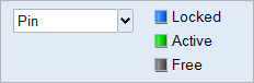
- Joint Type
- Joints are available in a variety of types such as Pin, Hinge, or Ball and Socket. The types available vary based on the feature where the joint is being applied.
- Joint State
- Each joint has a state which can be set to Locked, Active, or Free.
- Select Locked to prevent movement in the joint.
- Select Free if you want the mechanism to behave as if the joint is not there.
Note: Refer to Joint Types and States
for more information.
Joint Properties
Refine the behavior and appearance of joints using the joint properties available in the Property Editor (F3).
- Connection Stiffness
- Change how connection stiffness is defined for grounded joints (for structures analysis only).
- Flip Part Order
- Change the order of two parts in a given joint. This is useful when you want to invert a curve (such as action forces vs. reaction forces).
- Behavior
- Define joints as rigid, flexible, or virtual. Virtual is an expert option that is very similar to a rigid joint, but with "soft constraint" behavior that is useful for avoiding redundant joints. Default uses the global setting from the Run Motion Analysis window.
- Friction for Motion
- For rigid or virtual joints you can apply joint friction, which enables additional properties.
- Motion Rates
- For flexible joints, there are options for specifying Global, Basic, and
Advanced motion rates. The Advanced option allows you to specify
independent stiffness and damping rates for the degrees of freedom of
the joint, as well as the angle of the local reference frame used by the
flexible joint. The angle can also be set using a graphical manipulator
in the Joints tool. Note: When you change the default motion rate values to make a joint more flexible, it is likely that you will need to increase the Deformation Allowed setting in the Run Motion Analysis Settings window.
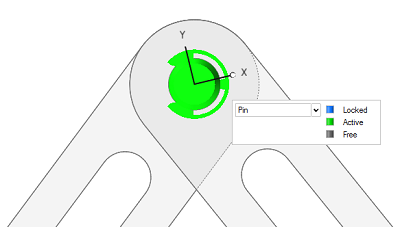 Figure 2. Joints tool angle manipulator for flexible joints
(advanced rate specification)
Figure 2. Joints tool angle manipulator for flexible joints
(advanced rate specification)
Note: Alignment Snapping to Edge for Flexible Joints: The
angle manipulator tool enables the x-axis to be easily aligned with another
arbitrary edge in the motion model. As you drag the manipulator over an edge,
the orientation of the x-axis snaps into alignment with the edge, and positive
(or negative) direction is controlled via proximity along the edge. For your
convenience, edge-snapping also works when you are aligning the arms on torsion
springs.
Joints Table
The Joints table lists all of the joints in your model including the type of connection, the parts it connects, and the assigned material.
Click the ![]() satellite icon on the Joints tool to display the table.
satellite icon on the Joints tool to display the table.
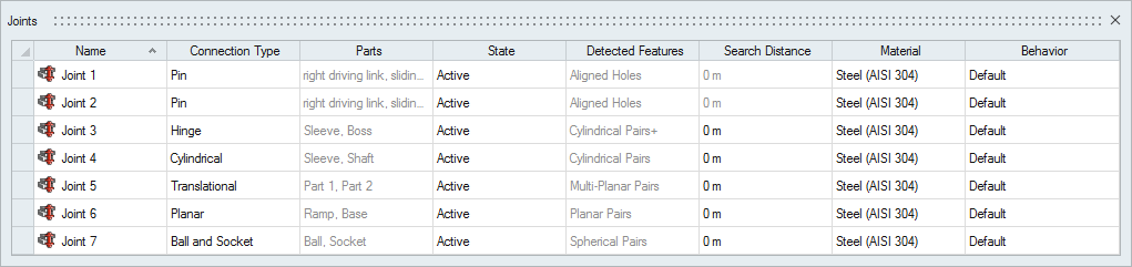
Figure 3. Joints Table
The table data can be edited with the following actions:
| To | Do this |
|---|---|
| Rename a joint | Select the cell in the table and then click again to make the field editable. |
| Change the connection type, state, material, or behavior | Select the cell in the table and then select a different option from the list. |
| Sort a column | Click the column header. Click repeatedly to toggle between ascending and descending order. |
| Add or remove columns | Right-click on a column header. |
Note: The Search Distance listed in the Joints table shows the minimum separation (the exact
minimum distance between the two parts). The search distance for an individual joint defined
in this table will override the global search distance defined in the Find Options on the
guide bar. The search distance is ignored when the Detected Feature type is aligned holes or
single holes.
Shortcuts
| To | Do this |
|---|---|
| Add a hole to the selection | Hold down the Ctrl key and left-click an unselected hole. The hole turns red. |
| Deselect a hole | Hold down the Ctrl key and left-click a selected hole. |
| Create a joint | Left-click a selected (red) feature or hole. |
| Isolate a joint | Press I to zoom in on the selected joint and its dependent parts. This works from the modeling window, Model Browser, and the Joints table. |
| Exit the tool | Right-click and mouse through the check mark to exit, or double-right-click. |