FEA topology for reanalysis provides an iso-density surface based on the volumetric
density information from a topology optimization. Through tetrameshing for 3D models and
inheriting boundary conditions, the results from FEA topology can be used for quick
reanalysis.
FEA topology can handle both shell and solid elements. For 3D models, the recovered
iso-surface can be tetrameshed-by-property automatically. FEA topology provides two options
for the processing of non-design elements:
Keep smooth narrow layer
Retain an artificial layer of elements around the non-design space in the
interpretation.
Split all quads
Split quad elements in the non-design space, if present, to generate a tetra
connection between design and non-design regions.
FEA topology preserves boundary conditions by inheriting them from the original model
(<prefix>.fem). Those boundary conditions unattached to
nodes/elements after geometry recovery are deleted to ensure reanalysis.
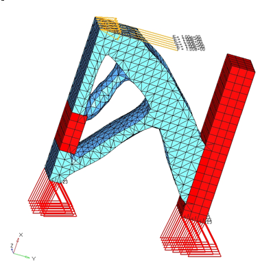
Figure 1
and Figure 2 show FEA topology for reanalysis with following input data definition:
File
block
Density threshold
0.300
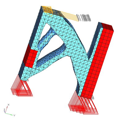
Figure 1 was run with Keep smooth narrow layer around disabled and Split to quads enabled. Figure 1. Result of FEA Topology for ReanalysisFigure 2 was run with Keep smooth narrow layer around enabled, and Split all quads
disabled. This approach creates a layer of elements around the non-design region and
pyramids around the quad elements, if quads exist, to connect to the design space
tetrahedral elements. Figure 2. Result of FEA Topology with a Layer of Elements around Non-Design Space
Tetramesh will be applied on the iso-surface result if there is one close volume at least.
The advantages of the tetramesh in FEA topology include:
Tetramesh can be performed by property.
The flexibility of controlling the number of tetramesh retries by perturbing the
density threshold value, in cases where tetramesh sometimes fails.