Connection
Connection check detects problems with parts/components such as bolts, nuts, clips, plates and reports the problems in a PowerPoint file.
There are multiple checks that can be performed, depending on the selection, the tool perform the checks and results of the checks are written out to the report files.
-
Click the folder icon and navigate to the model to import (Folder/File
selections).
The folder or the selected location must contain the spot weld file. The spot weld file type must be set in the config file.
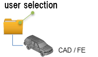
Figure 1. -
Click View Report to display the Summary PowerPoint
report.
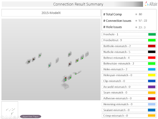
Figure 2. PowerPoint Summary . (Stored in Report Path)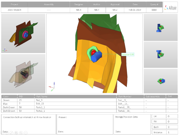
Figure 3. PowerPoint Detailed Report. (Stored in Report Path)
Output
Overview of the PowerPoint report generated from the Connection check.
A PowerPoint report is separated into several sections.
- Report Header
- Project name, assembly name and slide number.
- Full Assembly Picture
- Image of the components that have connection issues.
- H3D Image
- Section can be viewed in the HyperView Player, and shows an H3D image shows the FE model with the connections marked with Cross Hairs.
- Issue Details
- Details of components which have connection issues.
- User Review Section
- Used to add additional information when exchanging information with designers/engineers.
- Additional Info
- Occurrences of the issue shown in the current slide. The number of instances show the number of occurrences of the issue.
Supported Connection Checks
Types of checks to perform on connections in the model.
- Free Hole
- Detects the holes in the model which do not have connectors around
them.

Figure 4. - Free Bolt-Nut
- Detects the bolts and nuts which do not have corresponding holes to fit
in.
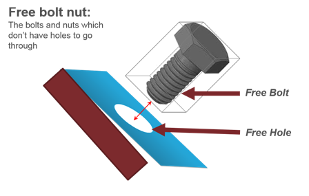
Figure 5. - Bolt Hole Mismatch
- Detects the bolts which have a hole around it, but the distance between
the bolt center and hole center is more than the threshold value.
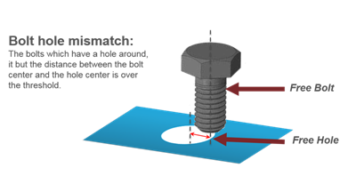
Figure 6. - Nut Hole Mismatch
- Detects the nuts which have a hole around it, but the distance between the nut center and the hole center is over the threshold.
- Bolt-Nut Mismatch
- Detects the bolt nut pairs whole location or alignment direction do not
match properly.
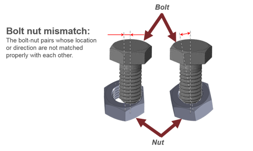
Figure 7. - Bolt-Nut Size Mismatch
- Detects the bolt nut pairs whose sizes are different from each other.
Note: The diameters of bolt, nut and clip are found through a CSV file.
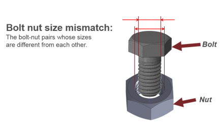
Figure 8. - Holes Mismatch
- Detects pairs of holes whose center axes do not match.
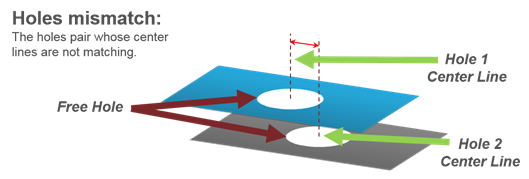
Figure 9. - Holes Pair Missing
- Detects the holes that do not have a corresponding pairing hole within
the specified tolerance.
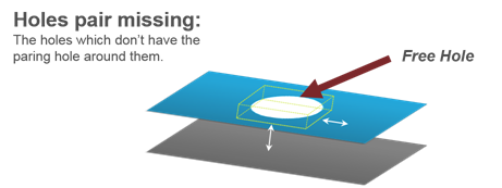
Figure 10. - Clip Mismatch
- Detects the clips which have a hole around it but the distance between the clip center and the hole center is over the threshold.