Radioss Connector Types
Supported Radioss connector types and property scripts.
Connector Types
- Radioss type2 (spring)
- Creates a SPRING2N element for the body and plot elements for the head, the plot elements are created for visualization purposes and find operations.
- This realization also uses the prop_type2.tcl1 property script.
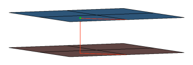
Figure 1.CFG radioss 2 type2 (spring) *filter spot *head plot 1 0 *body 0 spring 1 1 *post prop_type2.tcl - Radioss bolt (general)
- Creates RBODY elements for the head and SPRING2N body. The head elements project and connect to the nodes of the adjoining shell elements which form the hole. The connector location can either be on the edge of the hole, center of the hole, midpoint in between the two holes or on the second row of nodes which form the washer layer.
- This realization also the
prop_radioss_rigidupdate.tcl2 property script.
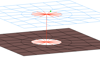
Figure 2.CFG radioss 52 bolt (general) *filter bolt *style bolt 0 *head rigidlink 1 10 *body 0 spring 1 1 *post prop_radioss_rigidupdate.tcl - Radioss hinge
- Creates RBODY elements for the head and SPRING2N body. The rot x degree of freedom is released so that the RBODY can rotate. The head elements project and connect to the nodes of the adjoining shell elements which form the hole. The connector location can either be on the edge of the hole, center of the hole, midpoint in between the two holes or on the second row of nodes which form the washer layer.
- This realization also the
prop_radioss_rigidupdate.tcl2 property script.
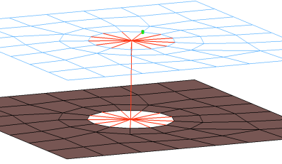
Figure 3.CFG radioss 53 hinge *filter bolt *style bolt 0 *head rigidlink 1 10 *body 0 spring 1 1 dofs=4 *post prop_radioss_rigidupdate.tcl - Radioss bolt (spider)
- Creates an RBODY element. The element projects and connect to the nodes of the adjoining shell elements which form the hole, the RBODY element is joined at the midpoint of the bolted connection. The connector location can either be on the edge of the hole, center of the hole, midpoint in between the two holes or on the second row of nodes which form the washer layer.
- This realization also the
prop_radioss_rigidupdate.tcl2 property script.
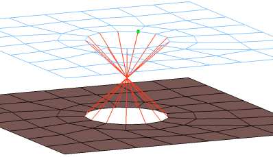
Figure 4.CFG radioss 54 bolt (spider) *filter bolt *style bolt 1 *head *body 0 rigidlink 1 1 *post prop_radioss_rigidupdate.tcl - Radioss bolt (cylinder rigid)
- Creates an RBODY element. Please reference “Cylinder Bolt” help for further details.
- This realization also the
prop_radioss_rigidupdate.tcl2 property script.
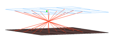
Figure 5.CFG radioss 60 bolt (cylinder rigid) *filter bolt *style bolt 3 *head *body 0 rigidlink 1 1 *post prop_radioss_rigidupdate.tcl - Radioss bolt (cylinder spring)
- Creates an RBODY elements and a zero length SPRING2N element. Please reference “Cylinder Bolt” help for further details.
- This realization also the
prop_radioss_rigidupdate.tcl2 property script.
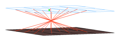
Figure 6.CFG radioss 61 bolt (cylinder spring) *filter bolt *style bolt 3 *head rigidlink 1 1 *body 0 spring 1 1 *post prop_radioss_rigidupdate.tcl - Radioss type2 (adhesive-spring)
- Creates multiple SPRING2N elements for the body and plot elements for the head, the plot elements are created for visualization purposes and find operations.
- This realization also uses the prop_type2.tcl1 property script.
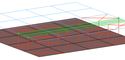
Figure 7.CFG radioss 62 type2 (adhesive-spring) *filter area *head plot 1 0 *body 0 spring 1 1 *post prop_type2.tcl - Radioss rigidlnk (midnode)
- Creates an RBODY with the independent node located in the middle between the two
parts. Both parts are connected to the RBODY via independent nodes. The needed sets
are created automatically.
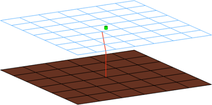
Figure 8.CFG radioss 63 rigidlnk (midnode) *filter spot *style mpc 2 *head *body 0 rigid 1 1 - Radioss HC cylinder rigid bolt
- This realization creates a single RBE2 for the body, and projects and connects the element to nodes of the adjoining shell/solid within the prescribed cylinder diameter, L1 (cylinder height along the vector from the connector location) and L2 (cylinder height in the opposite direction of the vector from the connector location).
- The realization uses the prop_radioss_rigidbolts.tcl3 property script.
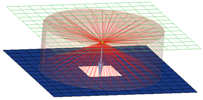
Figure 9.CFG radioss 64 HC cylinder rigid bolt *filter bolt *style bolt 4 *head *body 0 rigidlink 1 1 *post prop_radioss_rigidbolts.tcl - Radioss HC cylinder spring bolt
- This realization creates a SPRING element for the body, and projects and connects the element to nodes of the adjoining shell/solid elements with RBE2 elements within the prescribed cylinder diameter, L1 (cylinder height along the vector from the connector location) and L2 (cylinder height in the opposite direction of the vector from the connector location).
- The realization uses the prop_radioss_rigidbolts.tcl3 property script.
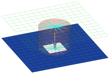
Figure 10.CFG radioss 65 HC cylinder spring bolt *filter bolt *style bolt 4 *head rigidlink 1 1 *body 0 spring 1 1 *post prop_radioss_rigidbolts.tcl - Radioss type2 (spring multiple row)
- Creates a certain pattern of SPRING2N elements.
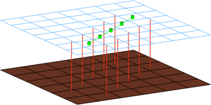
Figure 11.CFG radioss 66 type2(spring multiple row) *filter seam *style continuous 4 *head *body 0 spring 1 0 *post prop_type2radioss.tcl - Radioss type2 (spring single row)
- Creates a certain pattern of SPRING2N elements.
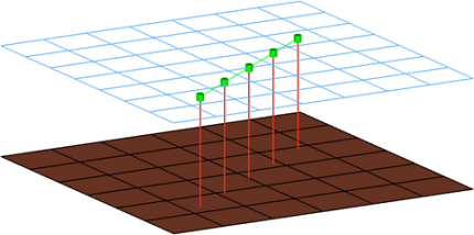
Figure 12.CFG radioss 67 type2(spring single row) *filter seam *style continuous 4 *head *body 0 spring 1 0 *post prop_type2radioss.tcl - Radioss bolt (2 cylinder rigid)
- Creates a RBODY per part with the center nodes connected to the SPRING2N element.
- Which nodes belong to the RBODY is determined with a defined cylinder volume. If a
hole per part can be found in the defined cylinder, only the nodes of the holes are
connected. Otherwise all nodes in the cylinder belong to the RBODY element (per
part).
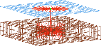
Figure 13.CFG radioss 68 bolt (2 cylinder rigid) *filter bolt *style bolt 5 *head rigidlink 1 1 *body 0 spring 1 1 *post prop_boltsradioss.tcl - Radioss HC hexa spotweld
- This realization creates various configurations of hexas for the body, and the hexas project and connect to the adjoining shell/solid elements by touching the shell/solid elements.
- This realization uses the prop_radiosshexa.tcl4 property script.
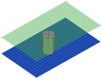
Figure 14.CFG radioss 69 HC hexa spotweld *filter spot *head *body 0 hex8 1 1 *post prop_radiosshexa.tcl - Radioss adhesive(contacts)
- This realization creates rows of HEXA and PENTA elements for the body. The HEXA and PENTA elements project and connect to the adjoining shell/solid elements by touching them.
- This realization uses the prop_pam_rad_adhesives.tcl5 property script the HC_HexaAdhesive.rad config file.
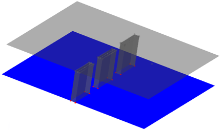
Figure 15.CFG radioss 70 adhesive(contact) *filter area *style adhesive 1 *head *body 1 hex8 1 1 penta6 1 1 *post prop_pam_rad_adhesives.tcl - Radioss acm(shell gap contact and coating)
- This realization creates hexa clusters between shell components. Contacts get defined between the shell components and the appropriate hexa nodes. A heat affected zone for the shells from ultra high strength steel material is created.
- This realization uses the
prop_rad_acm_shellgapcoating.tcl6 property script and the uhss_washersolid_matprop.rad
config file.
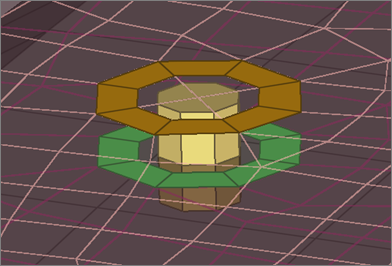
Figure 16.CFG radioss 71 acm (shell gap contact + coating) *filter spot *style acm 5 *body 0 hex8 1 1 *post prop_rad_acm_shellgapcoating.tcl - Radioss hexa(adhesive - shell gap)
- This realization creates rows of HEXA elements for the body. The HEXA elements project and connect to the adjoining shell/solid elements by touching them.
- This realization uses the prop_pam_rad_adhesives.tcl5 property script and the HC_HexaAdhesive.rad
config file.
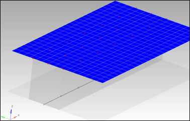
Figure 17.CFG radioss 72 hexa (adhesive - shell gap) *filter seam *style continuous 2 *head *body 0 hex8 1 1 *post prop_pam_rad_adhesives.tcl - Radioss hexa (tapered T)
- Intended to be used for t-cases. The size and exact position can be defined
thickness dependent, or the exact dimension and position parameters can be given.
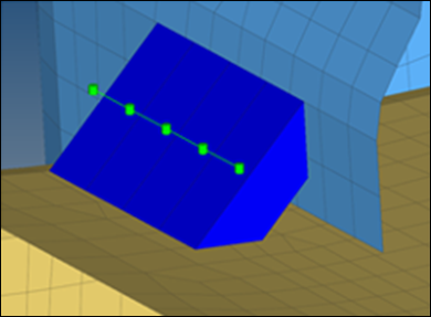
Figure 18.CFG radioss 105 hexa (tapered T) *filter seam *style continuous 6 *head *body 0 hex8 1 1
Automatic Exclusion of Special Nodes During Rigid Bolt Realization
- rigid links
- Rigids
- Rbe3 nodes
- boundaries condition
- IMPDISP
- IMPVEL
- IBVEL
- IMPACC
- FXBODY
- Nodes inside the Interfaces with Type2
Property Scripts
- prop_type2.tcl
This script is used while creation of RADIOSS [Type2 Spring] in the Spot panel.
This script does the following tasks:- Organizes the realized weld elements to the respective components based upon the link they are connected to. For example, if a weld is created between comp_1(1) and comp_2(2) it creates a component collector with the name RW^^_<id1_id2> and organizes all the welds created as links between these two components into this collector.
- Creates the following properties collectors:
- RW^^_<id1_id2>
- This property collector (with the P13_SPR_BEAM in case of R-BLOCK and SectBemSpr in case of R-FIX solver subtype) is associated with it as the card image.
- Creates sets in the following order:
- I1_M_<id1_id2>
- This contains the main as the FIRST link component ID to which the weld is connected to.
- I1_S_<id1_id2>
- This set contains the node ID of the projected spring element to the above component link as the secondary node N1.
- I2_M_<id1_id2>
- This contains the main as the SECOND link component ID to which the weld is connected to.
- I2_S_<id1_id2>
- This set contains the node ID of the projected spring element to the above component link as the secondary node N2.
- Creates two interfaces Groups (interfaces) for the spring weld elements created
between the same component links by the name
- RW^^1_<id1_id2>
- This references the above created sets that contain the ids of first node NI and first component Link C1.
- RW^^1_<id1_id2>
- This references the above created sets that contain the ids of second node N2 and second component Link C2.
- Creates a plot named Shear_Normal_Force_Plot with two curves from the Normal Force Function [named RW^^FN_1.0] and Shear Force Function [named RW^^FS_2.5], the values of which are read from the Radiossweld_config.ini file.
- prop_radioss_rigidupdate.tcl
This script is run for all the rigid/rigidlink weld configurations in the Radioss user profile. It creates the sets of all the secondary node ids of the rbodies created during the realization process, and assigns the GRNOD card image to them. It also updates some attributes of these cards.
- prop_radioss_rigidbolts.tclThe script performs the following tasks:
- Organizes the SPRING element into a component with the name HM_Bolt_SPRING.
- Organizes the RBE2 elements into a component with the name Realize#001 (# is a number starting with 2 and increments as 2, 4, 6, and so on).
- Creates a view with the name radioss_rigid_bolts.
Note: A new component HM_Bolt_SPRING will only be created if their is not a component with the same name that already exists; otherwise the existing component will be used. - prop_radiosshexa.tclThe script performs the following tasks:
- Organizes the hexas into a component with the name Realize_#001 (# is a number starting with 2 and incrementing as 2, 4, 6 for every new component).
- prop_pam_rad_adhesives.tclThe script performs the following tasks:
- Creates TYPE2 interfaces (groups) with the names ADHESIVES_CONTACTS_PID_=_#, which reference the independent/dependent links' main sets, and the nodes' slave sets (# is the ID of the links).
- Organizes the link entities (components, and so on) into sets with the names MAIN_PART_SET_PID, which in turn are referenced by the above interface groups (# is the ID of the link entity).
- Organizes the solids' nodes on links into sets with the names SLAVE_NODE_SET_PID_=_#, which in turn are referenced by the above interface groups (# is the ID of the link entity).
- Creates and assigns a property with the name Adhesive_Solid_Property and the card image P43_CONNECT to the solid component.
- Creates and assigns a material with the name Adhesive_Solid_Material and card image M59_CONNECT to the solid component.
- Creates a Failure Model with the name Failure_CONNECT_# and card image FAIL_CONNECT. The curves Adhesive_Solid_Material_YsvsNormalElong and Adhesive_Solid_Material_YsvsTangentialElong are required for the material definition.
Note: For Radioss versions less than Block100 (Block51 and Block90), HyperMesh creates a property definition with the P14_SOLID card image, and a material definition with the M1_ELAS card image. - prop_rad_acm_shellgapcoating.tclThis script performs the following tasks:
- For each connected link the contact /inter/TYPE2/ gets created and is named
TYPE2_CONTACT_PID_<link ID>. The following sets are created and referenced.
- MAINPART_SET_PID_<link ID>
- In this set, which is referenced as the main by the above mentioned contact, the link entities like the component get organized.
- SLAVENODE_SET_PID_<link ID>
- In this set, which is referenced as the slave by the above mentioned contact, the hexa nodes projecting onto the main entities get organized.
- For each link combination the hexa clusters are organized into separate
components and named RAD_SOLID_SPOTWELD_PID_<link1 ID>_<link2 ID>. All
components are assigned the following material and property:
- RAD_SOLID_SPOTWELD_DEFAULT_MAT.
- This material is defined as /MAT/LAW59/.
- RAD_SOLID_SPOTWELD_DEFAULT_PROP
- This property is defined as /PROP/CONNECT/.
The default values are read from uhss_washersolid_matprop.rad in the installation.
- The heat affected zone elements (washer) are organized into one separate
component for each link from the ultra high strength steel material and named
RAD_WASHER_PID_<link ID>. All components are assigned the following material
and property:
- RAD_WASHER_MAT
- This material is defined as /MAT/PLAS_JOHNS/.
- RAD_WASHER_PROP
- This property is defined as /PROP/SHELL/.
The material and property values are read from uhss_washersolid_matprop.rad in the installation.
- For each connected link the contact /inter/TYPE2/ gets created and is named
TYPE2_CONTACT_PID_<link ID>. The following sets are created and referenced.