Set up a high pressure die casting simulation and see how to troubleshoot
it.
In this exercise, you will learn how to run an analysis and prevent typical casting
defects for the high pressure die casting process.
Model file is available in the tutorial_models folder in the
installation directory in Program Files\Altair\2021.1\InspireCast2021.1\tutorial_models\handle.x_b.
Import Geometry
Launch Inspire Cast.
Click Open Model on the Files icon and browse to the
tutorial model file in the installation directory, or drag-and-drop the file
into the modeling window.
Use the mouse and view controls to position the model.
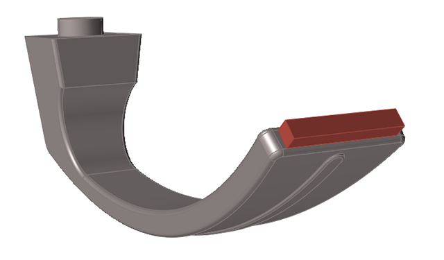
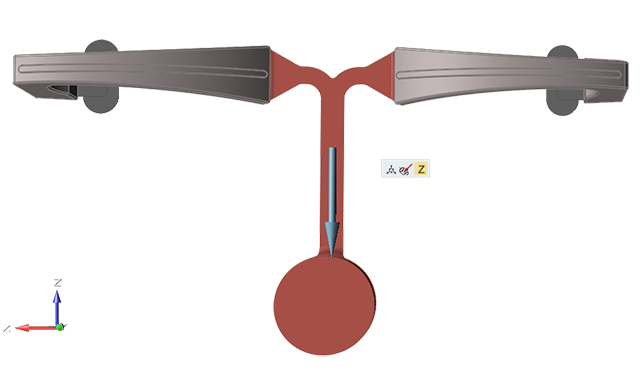
Designate a Cast Part
Click the Casting tab.
On the Cast Part icon, click Designate
Casting Part.
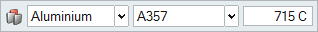
Click on the cast part.
Use the microdialog options to define the material, alloy, and
temperature.
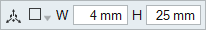
Create an Ingate
Click the Casting tab.
On the Gate icon, click Add/Edit
Gate.
Click on the part to create a virtual gate.
Use the microdialog options to define the position, shape, and
dimensions.
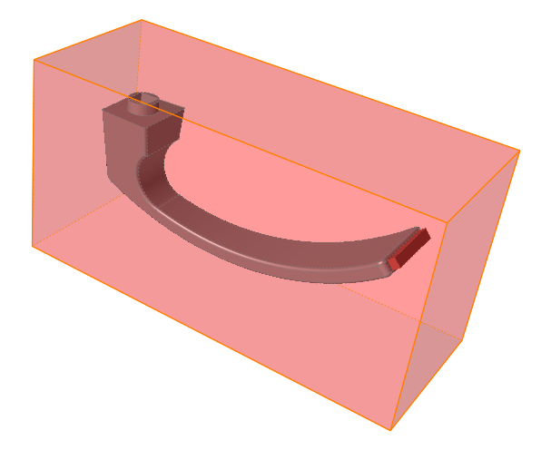
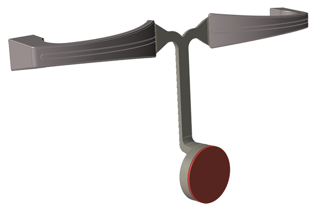
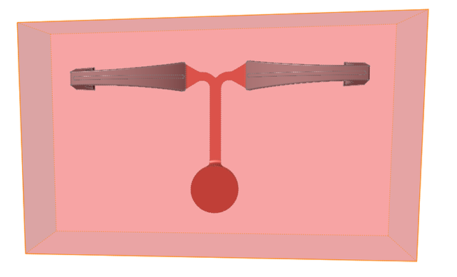
Create a Mold
Click the Casting tab.
Click the Components icon.
Click the Mold icon.
Define the mold material and temperature as shown.
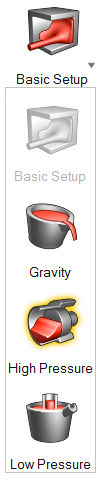
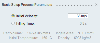
Configure Basic Setup
Click the Casting tab.
Click the Basic Setup icon.
Select Initial Velocity and enter 35 m/s.
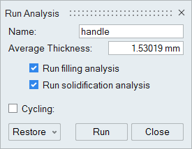
Run Analysis
On the ribbon, click the Casting tab.
On the Analysis icon, click Run
Analysis.
Select Run filling analysis and Run
solidification analysis.
Enter an average thickness of 1.53019 mm.
Click Run.
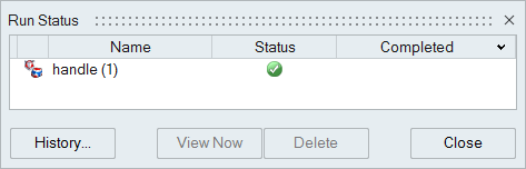
Note: Once the simulation calculation is finished, the green flag will appear on the
analyze icon.
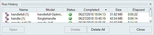
Note: The user can also select the results by clicking View
Now under Run History.
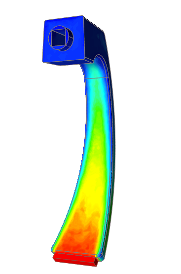
Run the Temperature Animation
Click Temperature under Result Types.
Click Play
to start the animation.
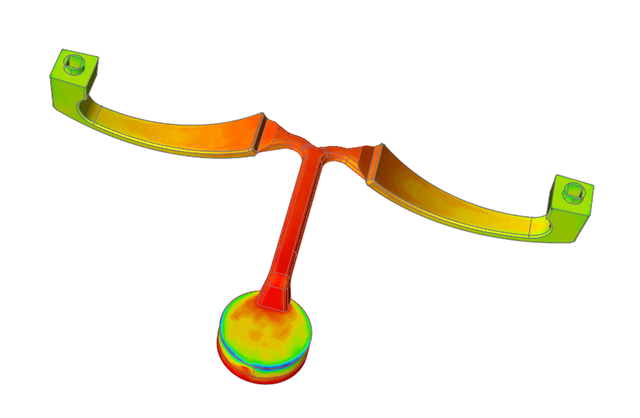
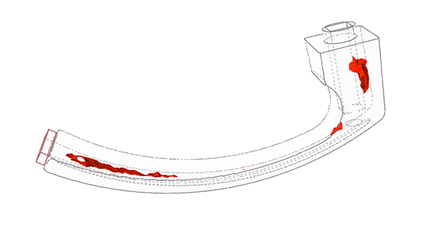
Run the Porosity Animation
Click Porosity under Result
Types.
Click Play
to start the animation.
Note:
To avoid defects like trapped air, we can optimize the design and use a
runner system.
To avoid porosity, we will add additional components which act as vents to
collect the trapped air.
Open the New Model
Click File>Open.
Browse to and select <installation
directory>\tutorial_models\handlefull.x_b
Cast Material and Temperature
Click the Casting tab.
On the Cast Part icon, click Designate
Casting Part.
Click on the cast parts.
Use the microdialog options to define the material, alloy, and
temperature.
Set Gravity Direction
Click the Casting tab.
On the Cast Part icon, click Set Gravity
Direction.
Use the microdialog options to rotate, align, or flip the model with respect to
the direction of gravity (the z-axis).
Right-click and mouse through the check mark to exit, or double-right-click.
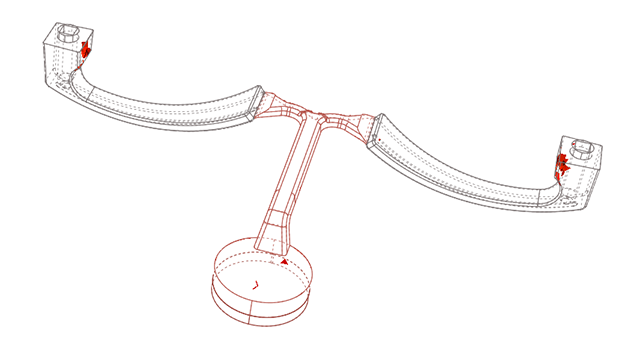
Designate Surfaces as Gates
Click the Casting tab.
On the the Gate icon, click Designate
Surfaces as Gates.
Click the predesigned gate.
Right-click and mouse through the check mark to exit, or double-right-click.
Generate a Mold
Click the Casting tab.
Click the Components icon.
Click the Mold icon.
Use the microdialog options to define the material and temperature.
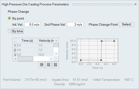
Configure High Pressure Parameters
Click the Casting tab.
Click to select the
High Pressure icon.
Select By point and enter an Init.
Vel. of 0.5 m/s and a 2nd
Phase Vel of 2 m/s.
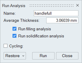
Run Analysis
Click the Casting tab.
On the Analysis icon, click Run
Analysis.
Select Run filling analysis and Run solidification analysis.
Enter an average thickness of 3.06039 mm.
Click Run.
Note: Once the simulation calculation is finished, the green flag will appear on the
analyze icon.
Note: The user can also select the results by clicking View
Now under Run History.
Run the Temperature Animation
Click Temperature under Result Types.
Click Play
to start the animation.
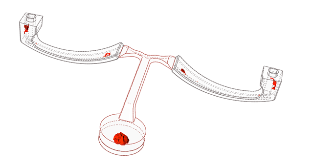
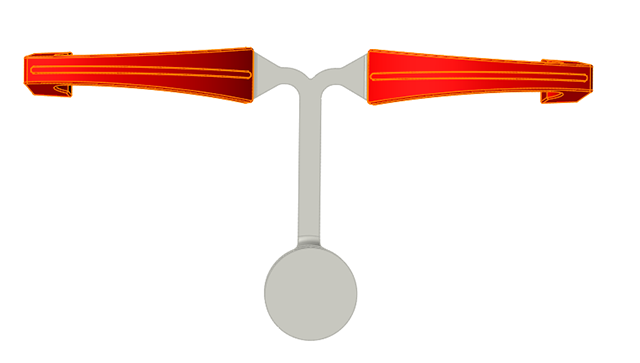
View Last Air Result
Click Last Air under Result
Types.
Note: The Last Air option shows where air will become
trapped during the filling process. When compared to the previous design,
air trapped inside of the casting is almost negligible while there is some
air in the vent system and filling system.
Run the Porosity Animation
Click Porosity under Result
Types.
Click Play
to start the animation.
Note: Compared to the previous design, there isn't any Porosity inside the
casting. Instead, it is inside the vent and filling systems.


 to select the
High Pressure icon.
to select the
High Pressure icon.