Release Notes: Altair Feko 2019.2
Altair Feko 2019.2 is available with a long list of new features, corrections and improvements. It can be applied as an upgrade to an existing 2019 installation, or it can be installed without first installing Altair Feko 2019.
Feko is a powerful and comprehensive 3D simulation package intended for the analysis of a wide range of electromagnetic radiation and scattering problems. Applications include antenna design, antenna placement, microstrip antennas and circuits, dielectric media, scattering analysis, electromagnetic compatibility studies including cable harness modelling and many more.
WinProp is the most complete suite of tools in the domain of wireless propagation and radio network planning. With applications ranging from satellite to terrestrial, from rural via urban to indoor radio links, WinProp’s innovative wave propagation models combine accuracy with short computation times.
Highlights of the 2019.2 Release
The most notable extensions to Feko and WinProp in the 2019.2 release.
Salient Features in Feko
- Significant improvements are included in the 2019.2 release that bring about better performance and a reduction in memory requirements for multiple solution methods. The multilevel fast multipole method (MLFMM) solution method boasts matrix fill times that are three or more times faster by utilising an efficient matrix fill strategy. The parallel scaling of the MLFMM is improved through reduced communication between processes, with the effect becoming more pronounced as the number of processes increase. Aperture to spherical mode source transformation is available for the MLFMM solution method. The time required to calculate the excitation vector is significantly reduced when the transformation can be applied. Total run time reductions of 30% to 50% were observed for example models. In addition to the improved performance, the fast far field calculation (employed for the MLFMM and other solution methods) uses 30% less memory than before. Optimisation of the adaptive cross-approximation (ACA) matrix fill stage provides a factor two improvement in performance. The ray launching geometrical optics (RL-GO) solution method now utilises shared memory containers resulting in reduced memory requirements for parallel simulations. A change to the ray storage strategy that avoids duplication of information greatly reduces the size of the .bof output file and also improves the performance of the RL-GO when the option to store the rays for processing in POSTFEKO is enabled.
- Model decomposition is made easier with the new Cartesian boundary near field request.
The request is defined by points on the surface of a cube (no points are calculated inside
the cube volume) and the surface can then be used as an aperture source in subsequent
models. The request also allows the user to exclude one or more of the surfaces where the
field is known to be zero, such as on a PEC ground plane. The workflow is considerably
simplified compared to defining the rectangular surfaces manually and then ensuring that
all the surfaces are correctly positioned and oriented to form the aperture source.
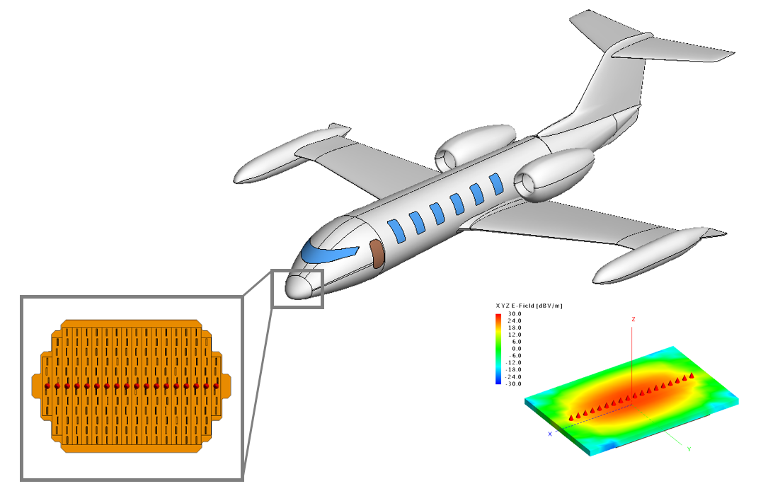
Figure 1. An example of a weather radar in an aircraft radome where the Cartesian boundary near field request can be used to simplify model decomposition. - The finite element method (FEM) solution method is extended to allow transmission lines
and non-radiating networks that connect to different FEM ports. Previously the networks
could be defined on a single FEM port, but connecting different FEM ports together was not
supported. Feed structures and filters (circuits) can now be connected to the FEM model.
These complex FEM components can be used in a larger MLFMM model, improving the MLFMM
convergence by encapsulating the complex component in the FEM region.
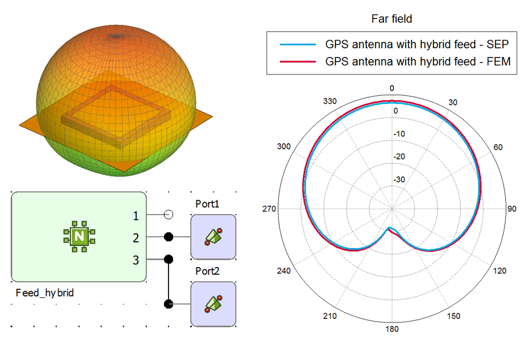
Figure 2. A GPS antenna with feed network solved with the MoM (SEP) and the FEM. - Two new features are added to the Cartesian surface graph allowing better data
representation and evaluation. The surface graph, similar to the 3D view display,
interpolates between values to show continuous results as a smooth surface. A discrete
display option is added for cases where continuous results are not applicable. When the
aspect ratio of the X and Y axis is important, the aspect ratio can be locked to avoid
distortion of the image.
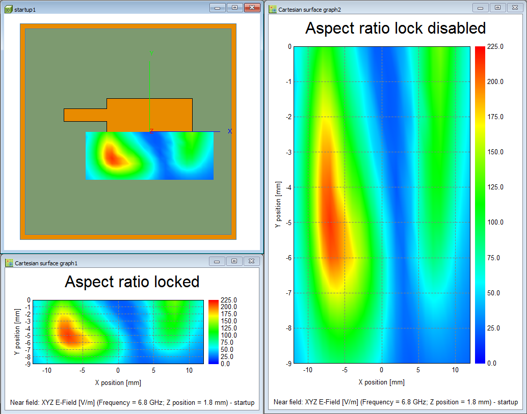
Figure 3. The aspect ratio of a surface graph can be locked. - The voltage controlled voltage source (VCVS) and transformer components are introduced
for the cable schematic editor. These components allow one-directional and bi-directional
coupling of currents inside the cable shield to the outside of the cable shield to model
the effects of imperfect cable terminations. It is crucial to model the cable terminations
precisely to obtain accurate results. The cable solution is also extended with a circuit
crosstalk calculation option that takes the geometry (installation) into account to
determine the cable per-unit-length parameters, but does not include 3D field coupling
between the harness and the installation. This option is useful when only the terminal
voltages and currents are of interest and 3D field coupling effects can be
disregarded.
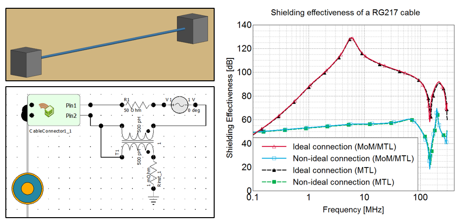
Figure 4. A non-ideal cable termination modelled using the new transformer component.
Salient Features in WinProp
- WinProp is enhanced with the ability to perform 5G network planning analysis. Dedicated 5G air interface files (wireless standard files) are shipped with the examples. When a new project is created with one of these files, the graphical user interface offers 5G options such as numerology, 5G carrier bandwidths, larger number of subcarriers, advanced transmission modes, which are then taken into account in the analysis.
- Support is added for predictions on a trajectory with varying heights for indoor and
rural scenarios.
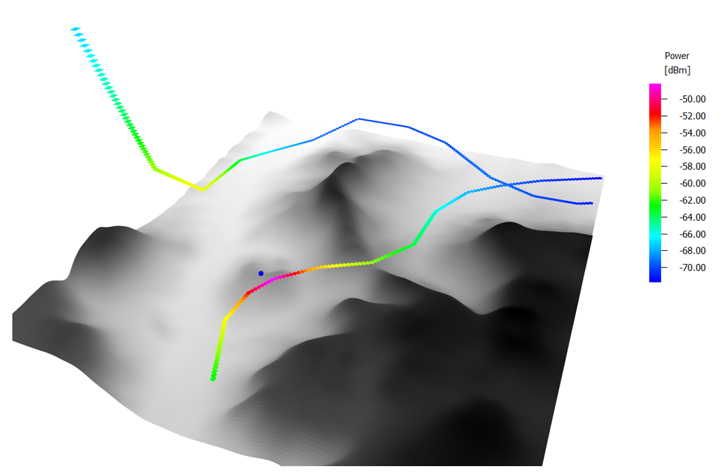
Figure 5. Trajectories are no longer limited to a fixed height above ground. - The speed of propagation predictions is improved by accelerating the line-of-sight analysis between transmitter and receiving points, for different types of databases (vector, pixel, topography) and all scenarios (indoor, urban, rural). A speed-up factor of two times or more is achievable for the start-to-finish simulation for various propagation models. Furthermore, the accuracy is improved for different propagation models as more valid interaction points are obtained with the new implementation. The increased accuracy is especially apparent for problems involving topography or urban vector databases.
- Standard ray tracing (SRT) is accelerated through the use of more efficient algorithms. In combination with the faster line-of-sight checks, a speed-up of an order of magnitude is possible.
Feko 2019.2 Release Notes
The most notable extensions and improvements to Feko are listed by component.
CADFEKO
Features
- Extended cable modelling with the following:
- Introduced voltage controlled voltage source (VCVS) and transformer components for cable schematics. These components can be added to cable terminations to define coupling between the inside and outside problems over a cable shield.
- Added the Circuit crosstalk option to the Solution tab of the Modify cable harness dialog. This option enables the calculation of intra-cable coupling inside the cable harness.
- Added the ability to increase the Cable per-unit-length parameter accuracy from Normal (default) to High or Very high. This setting is specified on the cable type definitions, for example, the Create ribbon dialog.
-
Coaxial cables using the Specify cable characteristics definition type are now specified by magnitude of characteristic impedance, attenuation and velocity of propagation. The phase of the characteristic impedance and real part of the propagation constant input fields are removed from the Create coaxial cable dialog.
The properties of cables using the deprecated definition will be converted to the new definition assuming a frequency of 1 kHz and the phase of the characteristic impedance is set to 0.
The API methods AddCoaxialUsingCharacteristics and AddCoaxialUsingCharacteristicsWithCoating have been deprecated and will trigger errors when used. Please update Lua scripts with AddCoaxialUsingPropagationCharacteristics and AddCoaxialUsingPropagationCharacteristicsWithCoating.
- Extended near field requests to support a Cartesian boundary definition method that allows specifying the field points on the bounding faces of a box.
- Upgraded the meshing library, bringing improvements such as the better handling of helical structures. The upgrade provides a fix for a meshing issue that could result in no mesh for a helical face or a mesh for a helical cutout instead of the geometry surrounding the cutout.
- Extended the CADFEKO API by adding the ClosestVertexTo method to the MeshTetrahedra, MeshTriangles and MeshSegments objects. This method can be used to obtain a mesh vertex located near a specified point.
Resolved Issues
- Fixed the problem that the Ctrl+Shift+A keyboard shortcut did not select all items belonging to the same part as a face, edge or region selected in the tree. Extended the Ctrl+Shift+A functionality to support selection in the 3D view for all selection types. In addition to faces, edges and regions, this shortcut can now also be used to select mesh labels, mesh elements and mesh vertices. The Select all and Select all in part options are available in the applicable 3D view and tree context menus.
- Resolved a problem where mesh wires were not highlighted in the 3D view when selecting an option applied to wires (such as Windscreen solution elements) on the View by solution parameters dialog.
- Fixed the colouring of cable shield media in the cable cross-section preview on the Modify coaxial cable dialog.
- Corrected the icons used for coaxial cables in the model tree. Before, the Predefined coax icon was displayed in the tree for Specified coax cables using the Specify cable characteristics definition type (instead the Specified coax icon).
EDITFEKO
Features
- Extended the CI - Cable interconnection/termination definition card to support voltage controlled voltage source (VCVS) and transformer components at cable terminations.
- Added the Circuit crosstalk option to the CS - Define cable path section card. This option enables the calculation of intra-cable coupling inside the cable harness.
- Extended the CD - Cable cross section definition card to allow for changing the Cable per-unit-length parameter accuracy from Normal (default) to High or Very high.
-
Changed the Coaxial cable characteristics definition on the CD - Cable cross section definition card to use magnitude of characteristic impedance, attenuation and velocity of propagation. The phase of the characteristic impedance and real part of the propagation constant input fields are removed from the dialog.
When pressing F1 to modify an older CD card, an error message will be displayed, after which the properties will be converted to the new definition assuming a frequency of 1 kHz. The phase of the characteristic impedance is set to 0.
- Extended the FE - Calculate the near fields card to support Cartesian boundary near fields that allows defining a near field request as the bounding faces of a box.
POSTFEKO
Features
- Added the functionality to lock the aspect ratio of a Cartesian surface graph. The default Auto lock aspect ratio setting locks the aspect ratio of a surface graph in certain cases, for example, when both axes are set to a unit of distance. Aspect ratio locking can also be purposely enabled or disabled for a surface graph.
- Introduced a discrete, non-interpolated rendering option for results plotted on Cartesian surface graphs.
- Changed the 3D view display of RL-GO rays to show a single ray by default. Select the All checkbox above the list of rays on the result palette to display all rays.
- Added data rate (bit/s) as a unit that can be used when importing and scaling data.
- Added support for exporting stored transmission/reflection coefficient data to .tr file.
- The .fek file version is increased to 169 to accommodate new features.
- Added support for viewing probe results for voltage controlled voltage source (VCVS) and transformer components.
- Added the functionality to support the new near field type using the Cartesian boundary coordinate system.
- Added support for the import and export of .efe and .hfe files containing Cartesian boundary near field requests.
Resolved Issues
- Fixed an assertion that failed with the message that Two ribbon tools are trying to use the same state widget (Greyscale) at the same time. This could be encountered when clicking on the window tab to switch from a 2D graph to a 3D view after making a change to a trace on the 2D graph.
- Fixed a display issue with non-radiating networks and transmission lines that surfaced on certain port types when a scale factor was applied.
- Updated the ribbon to allow adding characteristic mode results to a Cartesian graph from the Trace tab.
- Updated the parameter sweep script to support combining data from finite antenna array models using the domain Green's function method (DGFM).
Solver
Features
- Added support for the computation of near field requests based on a Cartesian boundary definition method that allows specifying the field points on the faces of a cuboid.
- Added support for transformer and voltage controlled voltage source (VCVS) components to allow coupling between inner and outer problems, at the terminations, to be taken into account during analysis of a cable.
- Improved the performance of the combined MoM/MTL solution method for cases with multiple cable harnesses where radiation is considered.
- Added support for user-specified mesh settings of 2D cable cross sections. Three options with increasingly fine meshing and thus improved accuracy can be selected.
- Added support for the definition of coaxial cables based on attenuation and velocity of propagation. This replaces the propagation constant based coaxial cable definition in previous versions of Feko.
- Significantly improved the time-efficiency of the matrix fill stage of an MLFMM solution of a model using the EFIE, resulting in a significant reduction of the overall solution time.
- Improved the performance of an MLFMM solution by reducing inter-process communication when carrying out matrix-vector products with many parallel processes.
- Added support for equivalent source transformation when solving a model with impressed near field sources with MLFMM, resulting in a significant decrease of the time taken to evaluate the right-hand side vector, and a significant reduction of the overall solution time.
- Reduced memory requirements for far field calculations using the fast far field method for solutions other than MLFMM.
- Significantly improved the time-efficiency of the matrix fill stage of the ACA solution. A speed-up factor of about two times can be achieved for most cases.
- Significantly reduced the memory usage of parallel RL-GO simulations of models involving many requested field samples or many near field sources, through the use of shared memory.
- Significantly improved the performance of the ray export phase of an RL-GO solution of dielectric models on machines with the Windows operating system. Achieved a speed-up factor of about four times for dielectric models with a large number of rays.
- Significantly improved the time efficiency of the geometry checking phase of an RL-GO solution, with diffraction effects taken into account, of a problem with a large number of triangles. The scaling of the geometry checking phase, with respect to the number of triangles, is improved from linear to logarithmic scaling.
- Improved the matrix fill stage performance for large parallel MoM solutions.
- Added support for connecting FEM line ports with a non-radiating network.
- Changed the default preconditioner for FEM models to improve robustness of the solution as well as to obtain consistent behaviour between models solved sequentially and in parallel. Sparse LU-based preconditioners are now consistently selected by default, where ILU-based methods were sometimes used before. Additionally, a direct sparse solver is used, instead of an iterative solution, for first-order decoupled FEM models.
- Upgraded the MUMPS library used in the Feko kernel to version 5.2.1.
- Upgraded the default SPICE engine to HyperSpice Version 2019-33627.
- Upgraded the eigenvalue and eigenvector solution library to the latest version.
- The str2ascii tool is extended to support the latest .str file format (13).
Resolved Issues
- Fixed a bug that resulted in inconsistent results upon repeatedly running a diffraction enabled RL-GO model in parallel using shared memory.
- Fixed a bug that resulted in noisy monostatic RCS results when a model, meshed with curvilinear triangles, is solved using RL-GO with high convergence accuracy settings.
- Improved a noisy RCS response for some RL-GO models meshed with curvilinear triangles by improving the robustness of ray/curvilinear triangle intersection tests.
- Fixed a memory leak associated with far field requests in RL-GO models.
- Improved the robustness of continuous frequency sweep interpolation on real-valued quantities such as gain or power. Interpolation artefacts in the form of spurious peaks in the frequency response are no longer present. (ADAPTFEKO)
- Fixed a bug that resulted in incorrect port impedance values when re-using a .str file produced with Feko version 14.0.430-635, in a version later than Feko 2017.2.
- Fixed a bug that led to an error when calculating contributions from higher-order mode excitations in a coaxial waveguide port.
- Fixed a bug that resulted in the inability to visualise received power for subsequent receiving antennas in POSTFEKO, for cases where more than one receiving near field aperture, consisting of multiple faces, is defined within one configuration.
- Improved the parallel scaling of the “Calculation of matrix elements” stage of a MoM solution for some process grids. For instance, a simulation with 62 processes was previously a factor of about two times slower than one with 64 processes. This has now been fixed.
- Refined conditions under which a microstrip port may be used.
Shared Interface Changes
Support Components
Features
- Added the WinProp Getting Started Guide and WinProp Scripting and API Reference Guide to the Launcher.
- Added an example of how to define a time domain pulse mathematically using analytical functions in POSTFEKO to the Feko User Guide.
- Corrected the Feko User Guide to indicate that vias are added as wires between layers for ODB++ and 3Di file imports only. A single PCB layer is imported from a Gerber file. Vias are not supported for Gerber format.
Resolved Issue
- Resolved the issue that an incorrect proxy configuration could cause the Updater to hang. Pressing Cancel now takes effect, allowing the user to correct the proxy settings.
WinProp 2019.2 Release Notes
The most notable extensions and improvements to WinProp are listed by component.
General
Features
- Added an envelope pattern file, for 5G applications, to the set of examples in the help directory.
- An updated and unified WinProp Scripting and API Reference Guide is now available in PDF and as part of the HTML documentation.
- A WinProp Getting Started Guide is now available. The following
examples were added:
- Analyse a Wi-Fi router in a building.
- Analyse the indoor cell phone reception, set in an urban environment.
- Analyse base stations in a city, set in an urban environment.
Resolved Issue
- Fixed a problem whereby OptMan and CoMan did not return Hosted HyperWorks Units automatically when closed. (Note: The problem was limited to Hosted HWU).
ProMan
Features
- Enhanced WinProp with the ability to perform 5G network planning analysis. Dedicated 5G air interface files (wireless standard files) are shipped with the examples. When a new project is created with one of these files, the graphical user interface offers 5G options such as numerology, 5G carrier bandwidths, larger number of subcarriers, advanced transmission modes, which are then taken into account in the analysis.
- Modern 5G systems may utilize antenna beam forming at the base station to increase the antenna gain in the direction of a mobile station. WinProp offers users the option to specify beam forming gains for the serving cell and for the interfering cell, for the data channel and for the control channel. This simplifies the workflow by not having to specify all the detailed patterns and mobile station locations.
- Introduced the concept of “Envelope Antenna Pattern” to account for beam switching at the base station in 5G. The base station can be equipped with antenna arrays and with digital logic to generate the best beam to reach the user equipment. The envelope pattern is based on the collection of possible antenna beams at the base station. In this release, one envelope pattern is used for both Control and Data. For the next release, separate envelope patterns for Control and Data are scheduled to be implemented.
- The amount of overlap between sub-carriers of interfering cells can now be specified for LTE and 5G air interfaces.
- Accelerated standard ray tracing (SRT) through the use of more efficient algorithms. In combination with the faster line-of-sight checks, a speed-up of an order of magnitude is possible.
- Improved the speed of propagation predictions by accelerating the line-of-sight analysis between transmitter and receiving points, for different types of databases (vector, pixel, topography) and all scenarios (indoor, urban, rural). A speed-up factor of two times or more is achievable for the start-to-finish simulation for various propagation models. Furthermore,the accuracy is improved for different propagation models as more valid interaction points are obtained with the new implementation. The increased accuracy is especially apparent for problems involving topography or urban vector databases.
- Added support for predictions on a trajectory with varying heights for indoor and rural scenarios.
- The prediction height in point and trajectory modes can now be specified relative to floors (only for indoor scenarios), ground or sea level. This is also applicable for preprocessed databases.
- Added support for predictions based on an absolute height (as opposed to a height defined relative to the topology as before) for rural scenarios with all prediction models.
- Similar to rural and urban scenarios with topography, one can now specify heights in indoor scenarios with topography in more than one way: height above ground (or floor) or height above sea level.
- Added support for absolute prediction height definitions (specifically absolute height above sea level) for all propagation models in urban scenarios.
- Results along a trajectory and results in time variant projects, including ray interactions with surrounding buildings, can now be animated in the 3D view. The animation and snapshots thereof can be exported and saved to a video file and bitmaps, respectively.
- The phase of the antenna pattern at both the base and mobile stations is now considered when computing the overall contribution of rays at receiving point.
- The yaw, pitch and roll angles can now be specified when computing received power (and associated quantities) along a 3D trajectory.
- Increased the maximum number of reflections supported by the IRT propagation model from 6 to 20.
- Added an option to ignore the effects of the direct ray from transmitter to receiver for SRT and IRT indoor scenarios.
- Result plots with rays can now be animated in projects with time variance or with virtual drive tests.
- The position of the antenna can now be specified with sub-millimetre accuracy, up to a tenth of a millimetre.
- Improved the accuracy of channel capacity and channel condition number.
- Enhanced the rural ray tracing (RRT) computational method with knife-edge diffraction. Rural ray tracing has a limit to the number of interactions and could leave some locations without prediction. Knife-edge diffraction adds the necessary interactions to end up with predictions for the entire area of interest.
- The transmission matrix associated with each ray is now also written to the .str file exported during post-processing with RunMS. Additionally, information regarding the phase of each ray as well as Doppler shift is now also written to the .str file.
- Direction of arrival and direction of departure angles are now written, in radians, to the .str file for each computed path. Additionally, these values are also displayed in the ProMan GUI when visualising rays.
- The phase of the field strength is now written to the .str file for each computed path. Additionally, these values are also displayed in the ProMan GUI when visualising rays.
- For rural/suburban scenarios, a parabolic equation solution method is available.
- Improved the computation of interactions during standard ray tracing when an object is replaced by RCS data, to consider additional interactions after scattering. This leads to an increased number of paths from transmitter to the RCS object, resulting in improved delay spread calculation.
- RCS data associated with an object can now be plotted in ProMan.
- Added a GUI option to run all computations defined in a project, one after the other. The computation sequence is as follows: propagation (RunPRO), Mobile station post-processing (RunMS), network planning (RunNET).
- Improved importing measurement data into ProMan to consider the average value of multiple measurements at the same coordinate. Previously, the final measurement for a specific point was used.
- Modified indoor database preprocessing for IRT in point mode to be independent of a defined receiving point at preprocessing time. This improvement allows one to simulate different receiving points without the need to preprocess the database for each new point.
- The inclusion of topography from a pixel database in “indoor” scenarios has been enabled. This is a first step; rays in ray tracing models do not yet interact with the topography.
Resolved Issues
- Fixed a memory leak in SRT computations with scattering enabled.
- Fixed a bug that resulted in a simulation error, with a preprocessed database, when the selected prediction area is larger than the defined area during IRT preprocessing.
- Fixed a bug where computed results were not invalidated, in ProMan, upon changing the prediction model.
- Improved the functionality to import a transmitter from .csv file to automatically map imported quantities to valid ProMan properties. With this improvement, the order of imported items is no longer relevant, and it is now possible to import all or a subset of the quantities defined in the .csv file.
- Fixed a bug that resulted in some transmitters, for a project with multiple transmitters, not being displayed when viewing network planning results in a new window. Additionally, the mismatch in the name and orientation of the displayed subset of transmitters has also been fixed.
- Fixed a bug that resulted in an error during propagation modelling or post-processing due to a very small resolution being defined for point mode results. The point-mode resolution is now limited to a minimum of 2 cm. Note that point-mode resolution is only related to the size of the pixel displayed when loading results and larger resolutions are typically better for visualisation. The location of the point itself can be specified to sub-millimetre accuracy.
- Fixed a bug that resulted in the computed per stream received power being lower than the corresponding sub-channel power results for a few points along a trajectory, when the receiver at the mobile station consists of more than one antenna element.
- Fixed a bug that led to ray data not being saved in the .str file resulting in a crash in ProMan when attempting to display the aforementioned rays.
- Fixed a bug that resulted in a crash when viewing results and toggling between 2D and 3D view.
- Fixed a bug that could cause ProMan to crash when adding a cable from a Component catalog before other components were present.
- Fixed a crash in RunMS that could occur when computing the “stream” results.
- Fixed an occasional crash that could occur during RunMS in a rural project with topography.
- Fixed a bug in the consideration of diffraction effects, for multiple interaction points associated with a ray, during standard ray tracing.
- Fixed a bug that resulted in trajectory results always being computed at a default height of 1.5 metres, rather than the defined height of the trajectory. Such behaviour was present if one switched from area-wide simulation, with the prediction area defined as “Individual for each transmitter”, to trajectory mode.
- Improved the robustness and accuracy of predictions made with the COST Walfisch-Ikegami model by improving the method used to determine building attributes (for example, width and height). Predictions are now more accurate and especially robust in cases where the database has some defects such as a building being defined twice or a building with zero height. These defects are typically present in imported databases from various open source repositories.
- Fixed a bug that led to discontinuities in results obtained for indoor predictions based on a user-defined variable attenuation.
- Fixed a bug that could make Doppler shifts oscillate rapidly along a trajectory.
- Fixed a bug that resulted in computed pixels not being located along the defined trajectory, when the IRT propagation model is used.
- Depending on the user-defined boundaries of the prediction area, the underlying topography in a rural scenario could be shifted by up to half of the prediction discretisation. This is fixed.
- Keysight PROPSIM channel output is now given based on relative delays, with the first value starting at 0.
- Fixed a bug that resulted in offset of individual antenna elements, relative to the centre of the mobile station, not being correctly considered for the case of a varying directional vector along a trajectory. This is only applicable for the post-processing option with “Individual location offset for each element” specified as the type of receiving antenna.
- WinProp is now more tolerant of small format variations in .ffe files.
- Fixed a bug that resulted in the computed exclusion zones not being correlated to the population threshold defined in the EMC specifications.
- In Monte-Carlo analysis, the calculations of the Tx power load and the uplink noise rise are now more accurate.
- Improved the results display of a Monte-Carlo analysis. All categories of users are shown, and selected results are presented in terms of number of users rather than Erl/km2.
- Fixed a bug where the Monte-Carlo Analysis dialog for Traffic Definition could sometimes show the unit Erlang/m2 while the user had elected to work in Erlang/km2.
- Fixed a bug that resulted in vector buildings specified at an absolute height relative to sea level, being incorrectly displayed as relative to ground in 3D view.
- Fixed a bug that resulted in predictions of rural results on a defined absolute height above sea level being incorrectly displayed with a height relative to topography in 3D view.
- Fixed a bug that resulted in the height of prediction plane and point mode results not being scaled along with a scaling applied to topography in 3D view.
- Fixed a bug that resulted in a constant height being used during the computation of over-the-rooftop loss for an urban signal path with varying distance from the rooftops. The actual height of the path at every point is now used.
- Fixed a bug in the consideration of the azimuth rotation angle applied to an array of receiving elements at a mobile station when the post-processing option including Tx and Rx is used.
- Fixed a bug that resulted in topography not being correctly displayed in 3D view for very large areas.
- Fixed a bug that led to the incorrect detection of the edges of topography data defined in geodesic coordinates, resulting in an error during simulation.
- Fixed a bug when computing the transmission loss based on an empirical loss model. This affects cases where duplicate walls are present in a database as well as special cases where two transmission interaction points are collocated.
- Fixed a bug that resulted in a non-smooth variation of results in 3D view when there is a large difference between the resolution of the topography and that of the predictions for urban scenarios.
- Fixed a bug caused by the gain of a transmitter, imported from a .csv file, being set to a different value prior to network planning. This resulted in an error due to the mismatch between the gain used for propagation and network planning analyses.
- Fixed a bug that resulted in some predictions, such as the minimum number of interactions or the line of sight, not being computed for some rural scenarios involving clutter data.
- Fixed a bug that resulted in an error when subtracting point-mode results with the option Value (File, delog., incoherent).
- Log files of the post-processing stage with RunMS are now written in the specified output directory. These were previously written to a “PropName” directory.
WallMan
Features
- Enhanced the zoom capability in WallMan to enable zooming in on small geometry details.
- Modified indoor database preprocessing for IRT in point mode to be independent of a defined receiving point at preprocessing time. This improvement allows one to simulate different receiving points without the need to preprocess the database for each new point.
AMan
Resolved Issues
- WinProp is now more tolerant of small format variations in .ffe files.
- Fixed a bug whereby antenna pattern files with .pln file extension could be selected in AMan but the contents could not be read.
Application Programming Interface
Features
- Added support for network planning with a 5G air interface in the WinProp API.
- Added sample projects demonstrating the use of API for database preprocessing, database conversion, network planning and propagation modelling.