Computation of Each Ray’s Contribution
Mathematical background and equations show how WinProp calculates the contribution to the prediction for each ray.
The deterministic model uses Fresnel equations for the determination of the reflection and transmission loss and the GTD/UTD for the determination of the diffraction loss.1 This model has a slightly longer computation time and uses three physical material parameters (permittivity, permeability and conductivity). For details see Landron2.
The empirical model uses five empirical material parameters (minimum loss of incident ray, maximum loss of incident ray, loss of diffracted ray, reflection loss, transmission loss). For correction purposes or the adaptation to measurements, an offset to those material parameters can be specified.
The empirical model has the advantage that the needed material properties are easier to obtain than the physical parameters required for the deterministic model. Also, the parameters of the empirical model can more easily be calibrated with measurements. It is, therefore, easier to achieve high accuracy with the empirical model.
Both diffraction models are based on the angles shown in Figure 1
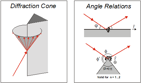
Figure 1. Angles for diffraction on a wedge.
For the empirical diffraction model the loss of the diffracted rays is computed depending on the angles and using the following equations:
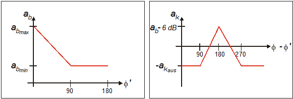
Figure 2. Empirical variation of the diffraction loss depending on the angle.
The angle dependencies are derived from the uniform diffraction theory (UTD) by the evaluation of measurements with different materials (brick, concrete) in an anechoic chamber and can be varied with the parameters , and within appropriate limits. With these three parameters, the model can be calibrated with measurements.
Breakpoint
In free space, there is a reverse proportional relation between the square of the distance from the transmitter to the receiver and the power at the receiver ( is the propagation factor):
To account for different propagation scenarios and to allow the user to manipulate the free space loss computation, the above conditions were considered by an extension of the equation:
With this approach a smooth transition of the free space loss is ensured. In general the breakpoint distance depends on the transmitter height, the height of the antenna at the mobile station and the frequency. The parameter BP is the breakpoint distance that is set to a default value according to the following formula:
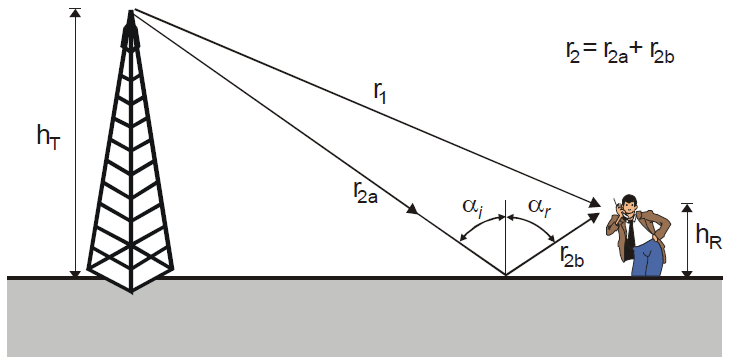
Figure 3. The breakpoint distance depends on the transmitter height, the height of the antenna at the mobile station and the frequency.
For distances larger than the breakpoint distance, the angles and approach 90° and the reflection coefficient approaches -1. The two rays approach destructive interference. The received power then depends on distance as indicated in Equation 7, where the exponent P2 tends to be significantly larger than the free-space exponent.
The parameters (exponent before breakpoint) and (exponent after breakpoint) can also be set by the user. The default values are and .