Rural Ray Tracing Model
The rural ray-tracing model is a (deterministic) multipath propagation model, considering phenomena like multiple reflections and wave guiding effects in canyons is required to obtain accurate predictions of the signal level and the spatial channel impulse response.
The wave propagation in rural and suburban scenarios is often characterized by multi path propagation due to interactions (reflections, diffractions, scattering) at various obstacles (hills, buildings, towers). Simple empirical propagation models for these scenarios do either ignore the topography between transmitter and receiver (Hata-Okumura model, empirical two ray model) or they consider only the shadowing due to obstacles in the vertical plane (deterministic two ray model).
More sophisticated approaches include multiple diffractions in the vertical plane (knife edge diffraction models) or they compute the wave guiding around obstacles in 3D (dominant path model). All these prediction models listed above are focusing only on a single propagation path. But in reality there are very often more propagation paths between transmitter and receiver. And only the superposition of all these paths leads to an accurate prediction. Therefore, ray-tracing models are available for rural scenarios.
WinProp offers rural ray tracing (RRT), which analyzes rays and interactions only in the vertical plane between transmitter and receiver, and standard ray tracing (SRT), which performs full 3D ray tracing. Rural ray tracing takes a limited number of interactions into account, and may not reach all prediction points by itself. Therefore, it has been enhanced with additional knife edge diffraction to predict propagation results for remaining locations.
Requirements
The approach of the rural ray-tracing model requires the conversion of the topography data (in pixel format) to a 3D vector data format. This step has to be made once for each scenario and can be done using the conversion functions included in WallMan. After conversion is done, the rural vector database is written to a file with the extension .tdv. This file has to be used to set up the rural simulation project if the rural ray-tracing should be used as propagation model.
- Topography: Topo maps must be converted from raster data to vector data using WallMan
- Clutter/land usage: Clutter maps must be converted from raster data to vector data using WallMan
- Vector objects: Additional vector objects (.idb files) can be added during the conversion using WallMan
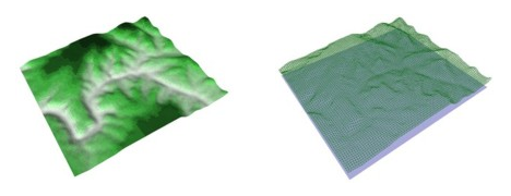
Figure 1. Topography database in raster format (on the left) and topography database in vector format (to the right).
Consideration of Land Usage (Clutter) Data
The additional consideration of land usage (clutter) maps is of course also possible. Similar to the topographical data, the clutter maps are also converted from raster data to 3D vector data taking account the clutter heights and the electrical properties of the materials defined for each clutter class individually. This approach allows a real 3D representation of the land usage maps.
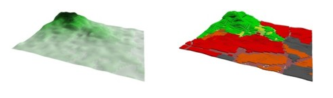
Figure 2. Raster topography without display of land usage (on the left) and raster topography with land usage in vector format (to the right).
Additional Obstacles
Beyond topography and land usage also arbitrary 3D vector objects can be defined in the scenario to model buildings, towers. These obstacles can either be converted from CAD data or they can be drawn in 3D with WinProp's CAD tool WallMan into the vector database. Of course the material properties of each 3D obstacle can be defined individually. The vector objects have to be saved in a regular indoor database file (.idb) and can be additionally considered during the conversion of topo and clutter data into the WinProp file format.
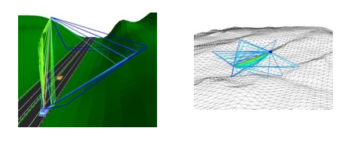
Figure 3. Predicted propagation paths in time-variant environment (on the left) and predicted propagation paths with wire frame topography (to the right).