Island
Calculate propagation in rural/suburban scenario for an island.
Model Type
The geometry is described by topography (elevation) and is shown in Figure 1. The Database tree in the Tree view enables you to change between topography (terrain elevation at every pixel) and clutter.
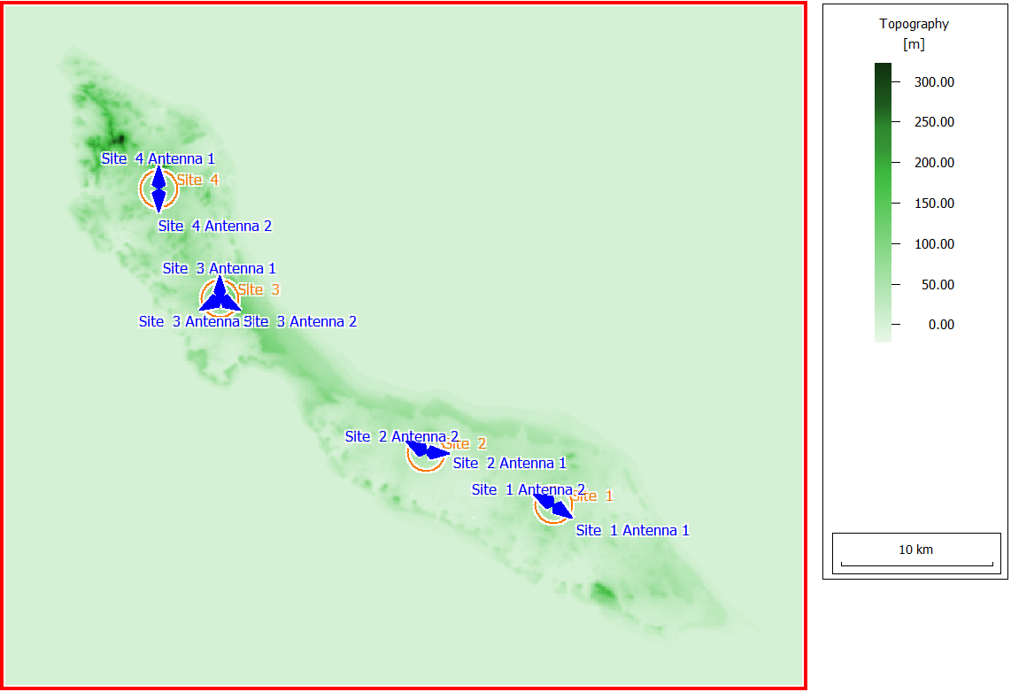
Figure 1. Topography (elevation).
Sites and Antennas
There are four antenna sites in this scenario. Site 3 has three sector antennas at 15 m height, and the other sites each have two sector antennas at a height of 25 m.
Computational Method
Results
Results are computed for each transmitter at a prediction height of 1.5 m. Propagation results include power coverage for each transmitting antenna of all four sites. This is the power that an isotropic receiver at a given position would receive from that transmitter. Propagation results also include field strength, path loss, line-of-sight, and number of interactions (such as diffractions) between transmitter and receiver. In Figure 2 and Figure 3, examples are shown of received power and number of interactions, respectively.
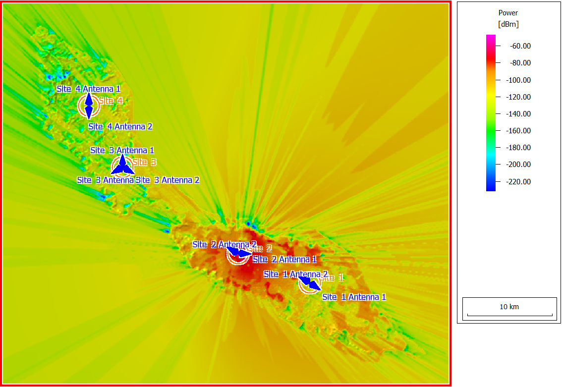
Figure 2. Power received from Site 2 antenna 1 by a hypothetical isotropic receiver at a height of 1.5 m.
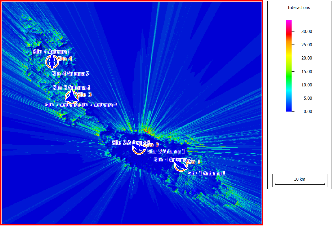
Figure 3. Number of interactions a signal undergoes between Site 2 Antenna 1 and each receiving location.