Create Surface Probes from Polyline
Use the Probes tool to create probes based on a polyline.
-
Use the Surface Probes tool to draw polylines.
-
From the ultraFluidX
ribbon, Setup group,
click the Output
tool.
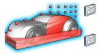
Figure 1. -
From the secondary tool set, click the surface probes of the
Probes tool.
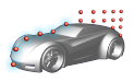
Figure 2. -
In the modeling window, click to place polyline
points on the selected surfaces.
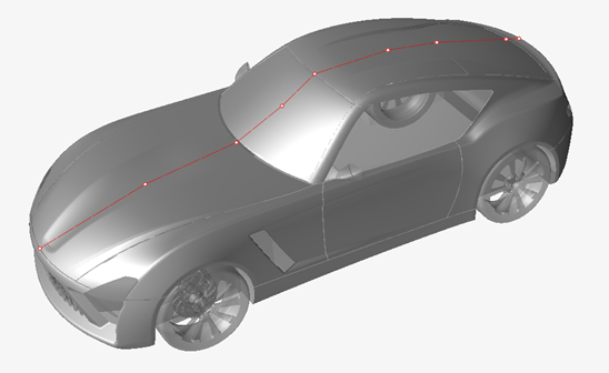
Figure 3.
Points are created along the polyline.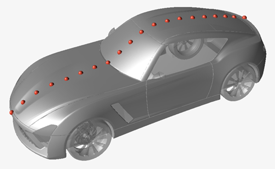
Figure 4. -
From the ultraFluidX
ribbon, Setup group,
click the Output
tool.
- Optional:
Define polyline settings in the microdialog.
- Define the output frequency.
- Define output start iteration.
- Set the number of probes along the polyline.
- Align the probes along a global axis.
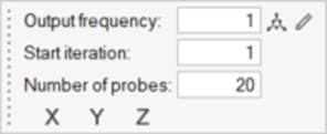
Figure 5. -
Move polylines in the modeling window.
-
In the microdialog, select
 .
.
- Use the graphical manipulators to move the polyline.
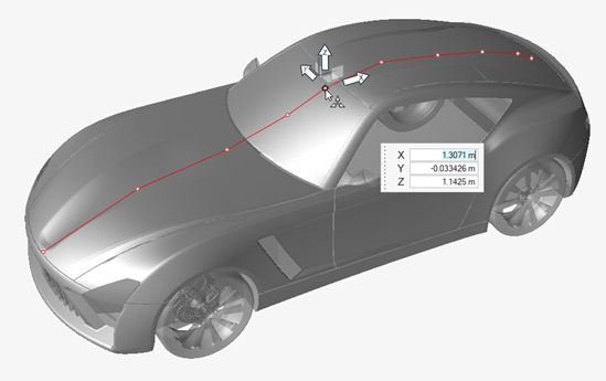
Figure 6. -
In the microdialog, select
-
Edit polylines in the modeling window.
-
In the microdialog, select
 .
.
-
Select an existing point along the polyline and use the graphical
manipulators to move the polyline point.

Figure 7.
-
In the microdialog, select
- Optional:
Export probes.
- From the legend in the top-left of the modeling window, right-click the active probe set and select Probes table from the context menu.
-
In the dialog, select
 to export surface probes.
Restriction: Importing surface probes is not supported when type = rake.For more information, see Import, Export, and Edit Output Controls.