Split Draw
A split draw direction is a type of manufacturing constraint, and is used when the parting plane between the halves of the mold lies inside the design space.
If you intend for a part to be manufactured by casting or machining it, the optimized shape must allow the two halves of the mold to separate after the part is formed. A split draw direction is used when the parting plane between the halves of the mold lies inside the design space. Both halves of the mold are pulled away from the design space in two different directions. This yields a slightly different result from a single draw constraint, as the two halves of the mold contain only a section rather than the entire design space. When defining a split draw direction on a design space, the optimizer determines the best location of the parting plane along the draw direction. You don't specify where the parting plane lies within the design space.
Split draw directions are valid for optimization but not analysis.
Apply a Split Draw
Select the Split Draw tool and click on a design space to apply a split draw constraint.
-
Click the Draw Direction tool on the Shape Controls
icon.

-
Click the Split Draw tool on the secondary ribbon.

Microdialog Options
Double-click a shape control to edit it and access the microdialog options.
| Icon | Description |
|---|---|
| Apply Draw Direction | Click to convert the split draw direction to a different type of draw direction. |
| Eliminate internal voids in the optimized part. | |
| Flip the draw direction. | |
| Rotate the shape control. | |
 |
Align a shape control to a design space after moving it. By default, shape controls are aligned to capture the most likely orientation for that particular design space as it is oriented in space. |
 |
Align a shape control to the global axes. |
Split Draw Examples
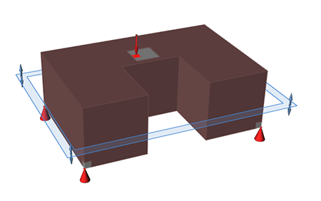
Figure 1. Design Space
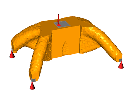
Figure 2. Optimized Shape with Split Draw Direction Applied
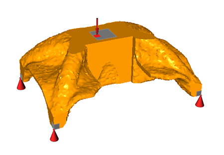
Figure 3. Optimized Shape with Split Draw Direction Applied and No Holes