Extrusion is a type of manufacturing constraint. It is similar to a single draw
constraint, but the profile of the resulting shape maintains a constant cross-section along
the draw direction.
Location: Structure ribbon, Setup group, Shape Controls icon
Due to the nature of the extrusion process, there will always be a hole in
extruded parts, so the No Hole option in the microdialog is not available. Extrusion
constraints are valid for optimization but not analysis.
Apply an Extrusion Constraint
Select the Extrusion tool and click on a design space to apply an extrusion
constraint.
Click the Draw Direction tool on the Shape
Controls icon.
Click the Extrusion tool on the secondary ribbon.
Click on a design space to apply an extrusion constraint.
A microdialog appears, along with a set of three orthogonal planes. The
active plane is shown in blue.
Select a plane to orient the extrusion draw direction.
Right-click and mouse through the check mark to exit, or double-right-click.
Tip: You can also right-click on a design space in the modeling window or in
the Model Browser and choose Shape Controls > Extrusion from the context menu.
Microdialog Options
Double-click a shape control to edit it and access the microdialog
options.
Icon
Description
Apply Draw Direction
Click to convert the extrusion constraint to a different type of draw
direction.
Rotate the shape control.
Align a shape control to a design space after moving it. By default,
draw directions are aligned to capture the most likely orientation for
that particular design space as it is oriented in space.
Align a shape control to the global axes.
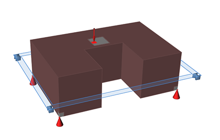
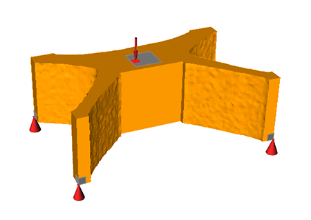
Extrusion Examples
Figure 1. Design Space Figure 2. Optimized Shape with Extrusion Applied