Stresses
The stresses are secondary results in a static analysis.
Stresses near notches and other sharp corners, point loads and boundary conditions, and rigid elements are often unreliable due to the singularities in these points. This is not a trait unique to OptiStruct, but is inherent in the finite element method itself. A mesh refinement in such places can improve the stress prediction. A theoretically infinite stress cannot be predicted by finite elements.
Stresses are primarily calculated at the Gauss integration points. These give the most accurate prediction. However, element stresses, corner stresses, and grid point stresses are provided.
Element stresses are calculated at the centroid of the element. They should only be post-processed using an assign plot. Contouring of element stresses vastly underestimates the extreme values due to the smearing across element boundaries.
The stresses of interest are usually found on the surface of a structure. Mesh refinement will actually not just improve the stress prediction but also change the location of the point of stress evaluation. Therefore, it is common practice to use a skin of thin membrane elements in 3D modeling, or rod elements in 2D modeling, to evaluate the stresses on element surfaces or edges, respectively. This method is accurate since it considers the correct condition of a stress-free boundary if no load is applied to the boundary. The method of skinning a model also has the advantage of much faster post-processing of solid models because only the membrane skin needs to be displayed.
Besides assign plots, elements stresses can be viewed in tensor plots that can help in the evaluation of the load path in a structure by evaluating the principal stress directions.
Corner stresses are computed by extrapolating the stresses from the Gauss points to the element grid points. Corner stresses are plotted in a contour plot. Corner stresses for solid elements are not available for normal modes analysis.
Grid point stresses are computed by averaging the corner stresses contributions of the elements meeting in a grid point. The averaging does not consider the condition of a stress-free boundary. Further, interfaces between different materials, where a stress jump normally can be observed, are not considered correctly because of the smearing of the stress. Grid point stresses are plotted in a contour plot.
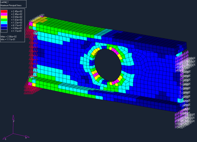
Figure 1. Assign Plot of Maximum Principal Element Stress