|
»Click here to display Table of Contents«
|

To translate data |

|

|

|

|
|
To translate data |
|
|
|

|
|
»Click here to display Table of Contents«
|
To translate data |
|
|
|
|
|
To translate data |
|
|
|
|
| 1. | Open the Translate panel. |
| 2. | Click the entity selector switch and select the data type of the entity you want to translate (nodes, surfaces, etc.) |
| 3. | Select the entities you want to translate: |
| • | Click the entities on your model in the graphics area. |
or
| • | Use the extended entity selection menu to choose a different selection method. |
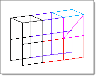
Selected entities highlight as shown above.
| 4. | Use the plane selector to specify the direction of translation. |
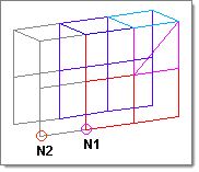
In this example, the translation will occur in the direction from N1 to N2.
| 5. | Click the toggle to select a method of specifying the translation magnitude. |
Either enter a numeric value into the text box after magnitude =, or use N2-N1 to translate your entities by the magnitude and direction of a vector defined by the N1 and N2 nodes chosen via the plane selector.
| 6. | Click the leftmost toggle to choose between using the global system or a local system of coordinates when translating entities. |
If you select local system, either click local system to enter the ID of the system, or click a local system in the graphics area. Next, click base node and enter the node ID to use as a base node, or click the desired node on your model.
| 7. | Click translate + or translate -. |
The selected entities move in the direction and magnitude defined in steps 4 and 5.
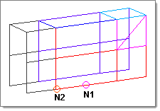
In this example, the selected elements have moved in the direction of N1 to N2.
Click translate - or translate + without changing any of the input data (for exampe use the same direction and magnitude settings).