|
»Click here to display Table of Contents«
|

Solid Meshing Wizard |

|

|

|

|
|
Solid Meshing Wizard |
|
|
|

|
|
»Click here to display Table of Contents«
|
Solid Meshing Wizard |
|
|
|
|
|
Solid Meshing Wizard |
|
|
|
|
The Solid Meshing Wizard is used to create solid (3D) mesh model data decks for RTM analysis starting from solids. It facilitates meshing solids in three ways. The wizard provides automatic 3D meshing of solids either with solidMap, tetMesh or CFD BL mesh. Every solid mesh is placed in a component collector with the name ComponentName_3DMeshtype#n, where 3DMeshtype is either of the solidmap, tetmesh ot BLmesh and n is an integer represents the ID of the respective solid in the model. The meshing algorithm meshes the solids in the following sequence, first solidmap solids will be meshed followed by tetmesh and finally end with CFD BL mesh In the case of RTM analysis, tetmeshing the components is sufficient and there is no need for CFD BL Mesh.
Clicking on the Solid Meshing Wizard macro opens the following dialog listing all the components which contains the solids one side and empty selected components list in the other side. Select the components to add them to the respective mesh type.
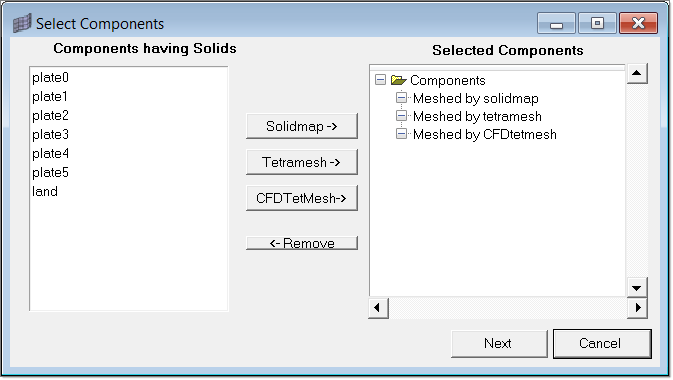
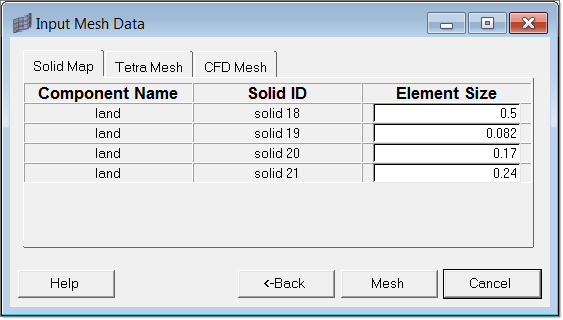
After adding the required components to the respective mesh type, click on Next. The following dialog displays. There are three tabs, one each for solid map, tetra mesh and CFD BL mesh as shown below.
The Solid Map and Tetra Mesh tabs list the selected components and respective solids with their IDs. It also shows the recommended element size for each solid.
The CFD Mesh tab lists extra meshing parameters apart from element size, as shown in the image below.
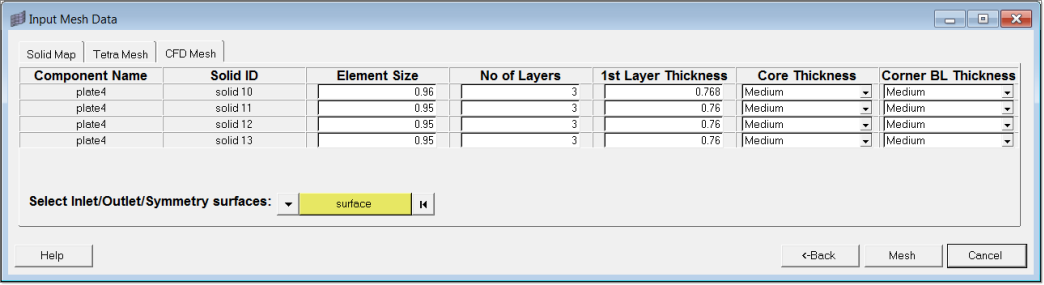
You can also select the inlet/outlet/symmetry surfaces of the CFD mesh. Refer the the CFD mesh online help for better understanding of the above mesh parameters.
The mesh completes when you click Mesh.