The second checkbox in the Extrusion Wizard is Set Analysis Requirements.
In the step, you will have to answer a series of questions to describe the model under consideration. Each equation has only two valid answers and the dialog will help you pick one of them. These requirement questions are grouped together.
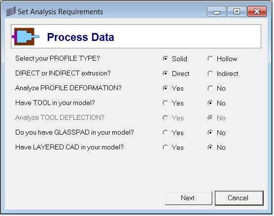
Process Data dialog
If your model has Tool, select Yes for the “Have TOOL in your model?” question. The “Analyze TOOL DEFLECTION?” option will be activated.
|
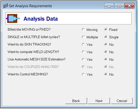
Analysis Data dialog
|
The Advanced Meshing Data dialog is invoked only when the answer to the question "Want to Control MESHING?" is Yes. In this panel, you can make your advanced meshing choices.
If you have a meshed model, select Yes for the "Have existing MESH in your model?" question. You can mesh the bearing region by solid map for both solid and hollow profiles. However, you are allowed to mesh billet by solid map only for solid profiles. It is also recommended that billet is not meshed using solid map. In addition, solid mapping is not always guaranteed to succeed in an automatic mode. This is due to the inherent complexity of this operation and its dependency on the geometry data. Despite this difficulty, if your bearing region is choked then you have no choice but to use solid map to create mesh in this region. This will allow the mesh to adhere to the choked geometry.
Click on Next to go to the next page for selecting the components.
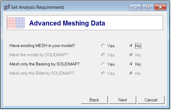
Advanced Meshing Data dialog - Optional
|
Select the components under Workpiece and Tool category according to what you have in your model. The components Billet, Bearing and Profile are always checked on by default. Click OK to save all the selections.
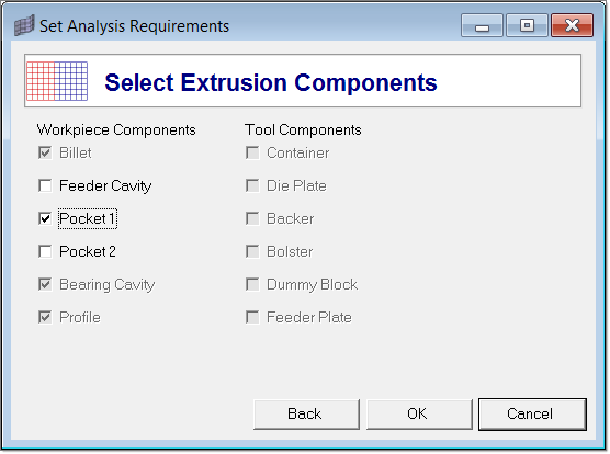
Select Extrusion Components dialog
| Note: | If you have a multi-hole die, then Pocket 1 regions of all the holes should be under a single component name Pocket 1. Same is case for Pocket 2 and Bearing. Pocket 1 and Pocket 2 are the two levels of pockets that are allowed for any class of die (this should not be confused with a multi-hole die). For example, if you have a 7-hole die with two pockets, then: |
| - | Pocket 1 will have all the pockets 1 regions corresponding to the 7 holes |
| - | Pocket 2 will have all the 7 pockets 2 regions |
| - | Bearing will have all the 7 bearing regions |
|


